Engine balance shaft structure

A technology for balancing shafts and engines, applied in mechanical equipment, vibration suppression adjustment, springs/shock absorbers, etc., can solve problems such as oil aging and acceleration, and achieve the effect of extending the oil change cycle, avoiding early wear, and compact layout.

Pending Publication Date: 2020-10-16
GUANGXI YUCHAI MASCH CO LTD
View PDF0 Cites 2 Cited by
  • Summary
  • Abstract
  • Description
  • Claims
  • Application Information

AI Technical Summary

Problems solved by technology

[0004] In view of the above-mentioned existing defects, the present invention provides an engine balance shaft structure, which solves the problem of accelerated oil aging of the balance shaft and improves the vibration damping effect of the balance shaft

Method used


Image

  • Engine balance shaft structure
  • Engine balance shaft structure
  • Engine balance shaft structure

Examples


Embodiment Construction

[0024] In order to describe the technical content, achieved goals and effects of the present invention in detail, the following will be described in conjunction with the embodiments and accompanying drawings.

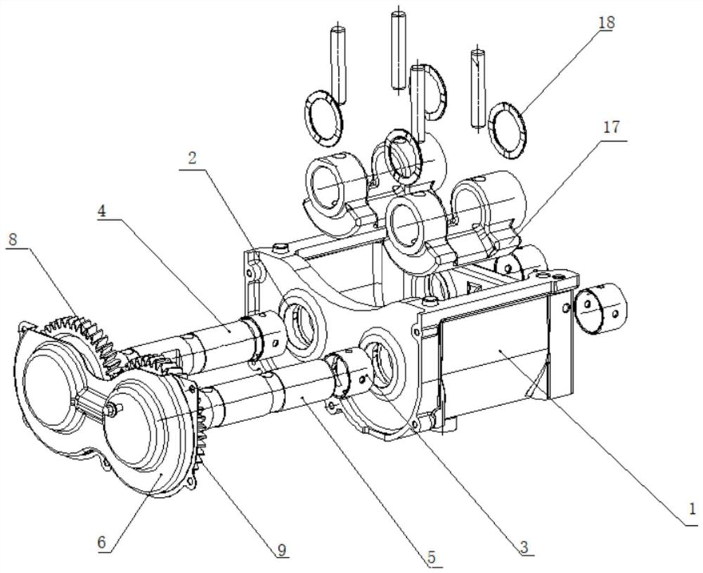
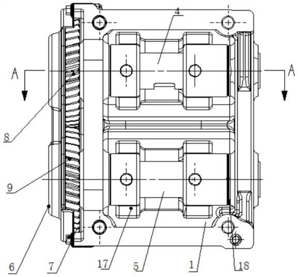
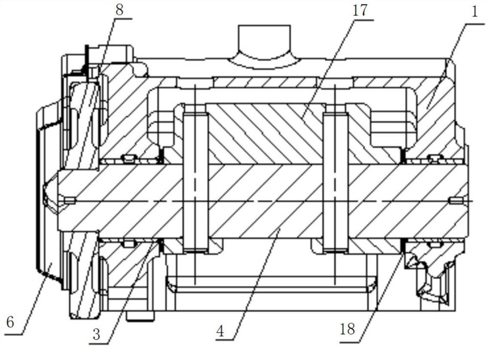
[0025] Such as Figure 1-3 As shown, the present invention provides an engine balance shaft structure, including a balance shaft chamber 1, a cover plate 6, a bearing bush 3, a first balance shaft 4 and a second balance shaft 5, a driving gear 8 and a transmission gear 9, Among them, the balance shaft chamber 1 is used as an installation carrier, integrating the oil circuit; the bearing bush 3 is installed on the bearing hole 2 of the balance shaft chamber 1, and forms a rotating pair with the first balance shaft 4 and the second balance shaft 5 at the same time; The gear 8 and the transmission gear 9 are installed on the first balance shaft 4 and the second balance shaft 5 respectively, and the gears mesh with each other and are located outside the balance shaft chambe...


PUM


Abstract

The invention discloses an engine balance shaft structure. The engine balance shaft structure comprises a balance shaft cavity; two corresponding bearing holes are formed in the two opposite side walls of the balance shaft cavity respectively, a first balance shaft and a second balance shaft are installed in the two bearing holes through bearing bushings respectively, and revolute pairs are formedamong the first balance shaft, the second balance shaft and the corresponding bearing bushings; a cover plate is arranged on one outer side of the balance shaft cavity, and the cover plate and the balance shaft cavity are connected with each other to form a gear cavity; a driving gear and a transmission gear which are meshed with each other are arranged in the gear cavity, inner holes of the driving gear and the transmission gear are fixed to one ends of the first balance shaft and the second balance shaft respectively, an oil way for lubricating the bearing bushings is arranged in the balance shaft cavity, and an oil return hole and an oil return opening are formed in the bottom of the balance shaft cavity and the bottom of the gear cavity respectively. According to the engine balance shaft structure, the problems of accelerated aging of engine oil of the balance shafts and low oil pressure of the bushings at the two ends are solved, and the damping effect of the balance shafts is improved.

Description

technical field [0001] The invention relates to the technical field of engine components, in particular to an engine balance shaft structure. Background technique [0002] The working principle of the double balance shaft is to eliminate or reduce the second-order reciprocating inertial force. The crankshaft drives the balance shaft mechanism to run. The speed of the balance shaft is twice the speed of the crankshaft. During the operation of the balance shaft, the inertial force generated by the rotation of the eccentric shaft and the second-order reciprocation of the engine Inertial forces are counteracted, thereby achieving a vibration damping effect. The eccentric structure has high requirements on lubricating bearings during high-speed movement, and a reasonable layout of oil passages can greatly improve the reliability of the balance shaft. [0003] In the existing balance shaft structure, the balance shaft parts are installed on the body, and the direction of the cham...

Claims


Application Information

Patent Timeline
Patent Type & Authority Applications(China)
IPC IPC(8): F16F15/26
CPCF16F15/265F16F15/267
Inventor 包毅徐雪松张锦苏怀林何化蔚兴建梁德浦
Owner GUANGXI YUCHAI MASCH CO LTD
Why Eureka
Try Eureka