
A positive pressure sealed cavity discharge condensed water structure

A technology for sealing the cavity and condensed water, which is applied in the direction of preventing condensed water, space heating and ventilation details, heating methods, etc., to achieve the effects of maintaining pressure balance, facilitating smooth discharge, good drainage and water sealing effect

Active Publication Date: 2022-04-22
合肥丰蓝电器有限公司
View PDF20 Cites 0 Cited by
  • Summary
  • Abstract
  • Description
  • Claims
  • Application Information

AI Technical Summary

Problems solved by technology

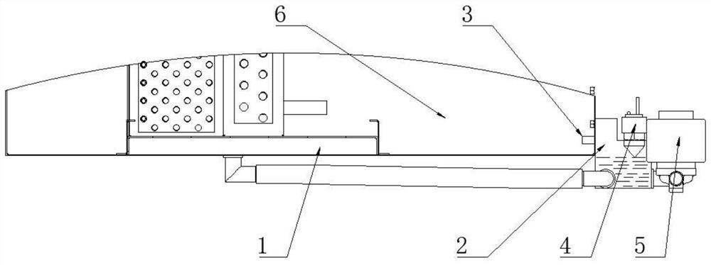
[0003] The purpose of the present invention is to provide a positive pressure sealed cavity to discharge condensed water structure, through a condensed water tank, a condensed water collection tank installed at the rear end of the condensed water tank, a pressure balance tube, a photoelectric liquid level switch and a drain solenoid valve , which solves the problem that the sealed chamber can ensure the smooth discharge of condensed water while maintaining the positive pressure seal

Method used


Image

  • A positive pressure sealed cavity discharge condensed water structure
  • A positive pressure sealed cavity discharge condensed water structure

Examples


Embodiment Construction

[0023] The following will clearly and completely describe the technical solutions in the embodiments of the present invention with reference to the accompanying drawings in the embodiments of the present invention. Obviously, the described embodiments are only some, not all, embodiments of the present invention. Based on the embodiments of the present invention, all other embodiments obtained by persons of ordinary skill in the art without creative efforts fall within the protection scope of the present invention.

[0024] In describing the present invention, it is to be understood that the terms "opening", "upper", "lower", "thickness", "top", "middle", "length", "inner", "surrounding" etc. Indicating orientation or positional relationship is only for the convenience of describing the present invention and simplifying the description, and does not indicate or imply that the components or elements referred to must have a specific orientation, be constructed and operated in a sp...


PUM


Abstract

The invention discloses a structure for discharging condensed water in a positive pressure sealed cavity, and relates to the technical field of condensed water discharging structures. The present invention includes a condensed water tank, the condensed water tank is installed inside the positive pressure cavity, a water collecting part is provided on one side of the positive pressure cavity, and the inside of the water collecting part communicates with the inside of the positive pressure cavity through a pressure balance pipe, and the water collecting The inside of the unit is also connected to the tank body of the condensate tank through the water inlet pipe; a liquid level switch is installed on the upper part of the water collection unit, and a drainage solenoid valve and an emergency drainage valve are installed on the drain pipe of the water collection unit. The present invention solves the problem that the sealing cavity can be sealed while maintaining positive pressure through a condensate water tank, a condensate water collection tank installed at the rear end of the condensate water tank, a pressure balance pipe, a photoelectric liquid level switch and a drain solenoid valve. The problem of smooth drainage of condensed water.

Description

technical field [0001] The invention belongs to the technical field of condensed water discharge structures, in particular to a positive pressure sealed cavity discharge condensed water structure. Background technique [0002] Now some environmental control systems for special occasions require the indoor environment to be strictly isolated from the outdoor environment, such as the environmental control system used in the sealed space in the heavily polluted outdoor environment. Maintain a certain positive pressure to ensure the sealing and airtightness of the cavity. In this context, the environmental control system needs to discharge the generated condensed water to the outdoor environment. In the prior art, the "U" type water sealing technology is often used to isolate the indoor and outdoor environments. This method has a good sealing effect when the cooling is turned on in summer, but there are heating conditions in winter or no condensed water is generated when the mac...

Claims


Application Information

Patent Timeline
Patent Type & Authority Patents(China)
IPC IPC(8): F24F13/22
CPCF24F13/222
Inventor 李军秦燕山丁希曙
Owner 合肥丰蓝电器有限公司
Learn More