Supercharge Your Innovation With Domain-Expert AI Agents!

Angle-adjustable photovoltaic support

A photovoltaic support and angle technology, which is applied to the support structure of photovoltaic modules, photovoltaic modules, photovoltaic power generation, etc., can solve the problems of excessive rotating mechanism structure, the photovoltaic support cannot be adjusted in height or adjust the structure, and is complicated, and achieves high sensitivity. Effect

Inactive Publication Date: 2020-10-16
ZHONGHUI ELECTROMECHANICAL TECH
View PDF0 Cites 0 Cited by
  • Summary
  • Abstract
  • Description
  • Claims
  • Application Information

AI Technical Summary

Problems solved by technology

[0004] The purpose of the present invention is to provide an angle-adjustable photovoltaic support, through the coordinated design of the electric turntable and the electric push rod, the problem that the existing photovoltaic support can only rotate in the plane and cannot perform three-dimensional angle adjustment in all directions is solved; The matching design of the column and the limit ring solves the problem of too many structures of the existing photovoltaic support plane rotation mechanism; at the same time, through this design, it solves the problem that the existing photovoltaic support cannot be adjusted in height or has a complicated adjustment structure; through the first The coordinated design of the first light tracking sensor, the second light tracking sensor and the controller solves the problem that the angle adjustment of the existing photovoltaic support is not sensitive enough

Method used


Image

  • Angle-adjustable photovoltaic support
  • Angle-adjustable photovoltaic support
  • Angle-adjustable photovoltaic support

Examples


Embodiment Construction

[0027] The following will clearly and completely describe the technical solutions in the embodiments of the present invention with reference to the accompanying drawings in the embodiments of the present invention. Obviously, the described embodiments are only some, not all, embodiments of the present invention. Based on the embodiments of the present invention, all other embodiments obtained by persons of ordinary skill in the art without creative efforts fall within the protection scope of the present invention.

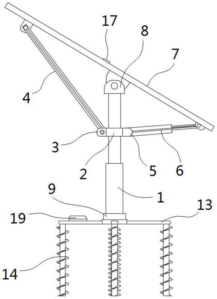
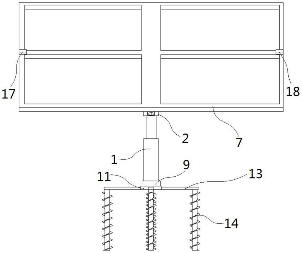
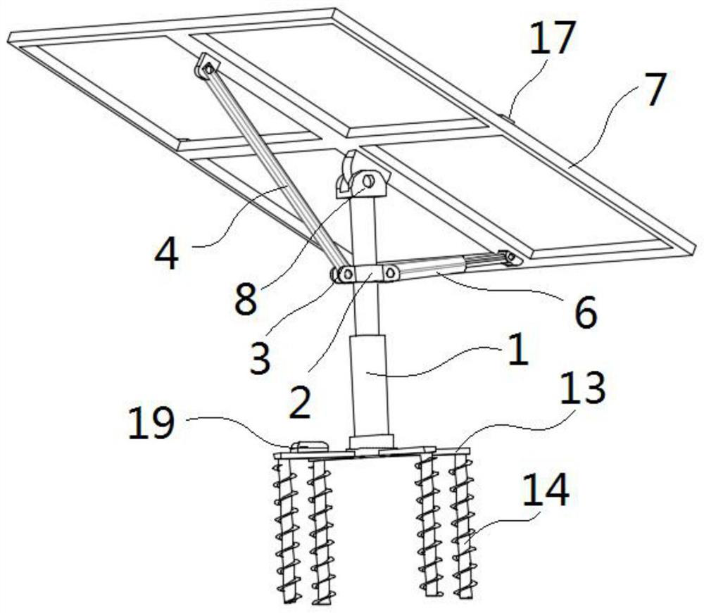
[0028] see Figure 1-7 , the present invention is an angle-adjustable photovoltaic support, including a telescopic column 1; the side of the telescopic column 1 is fixedly connected with a limit ring 2; the side of the limit ring 2 is fixedly connected with a first hinged seat 3; the first hinged seat 3 The two opposite inner walls are hinged with support rods 4; the surface of the limit ring 2 away from the first hinge seat 3 is provided with a fixing hole 5; the ...


PUM


Abstract

The invention discloses an angle-adjustable photovoltaic support, and relates to the field of photovoltaic technology. The angle-adjustable photovoltaic support comprises a telescopic column. The peripheral side face of the telescopic column is fixedly connected with a limiting ring. The peripheral side face of the limiting ring is fixedly connected with a first hinge seat. The two opposite innerwalls of the first hinge seat are hinged to a supporting rod. A fixing hole is formed in the surface, away from the first hinge seat, of the limiting ring. The peripheral side face of the fixing holeis fixedly connected with an electric push rod. One end of the electric push rod is hinged to a stand. The peripheral side face of the telescopic column is fixedly connected with a second hinge seat.The two opposite inner walls of the second hinge seat and the two opposite inner walls of the supporting rod are all hinged to the stand. The bottom face of the telescopic column is fixedly connectedwith an electric rotary disc. A plurality of connecting holes are formed in one surface of the electric rotary disc. The surface of the electric rotary disc is in threaded connection with a base through threaded rods. By means of the design of a lifting column and the limiting ring, the angle and height of the angle-adjustable photovoltaic support can be adjusted, and the problem that too many photovoltaic panels are located at the same height and block each other, and therefore the light source use ratio is decreased is solved.

Description

technical field [0001] The invention belongs to the technical field of photovoltaics, in particular to an angle-adjustable photovoltaic support. Background technique [0002] Solar photovoltaic support is a special support designed for placing, installing and fixing solar panels in solar photovoltaic power generation systems; the general materials are aluminum alloy, carbon steel and stainless steel. [0003] The angle of the solar photovoltaic module in the traditional photovoltaic support is fixed, and due to different geographical locations and different times, the angle of sunlight is different, and when the sun changes its position, the orientation of the solar photovoltaic support cannot be quickly adjusted, resulting in solar cells The panel has a low absorption rate of sunlight, which in turn affects the utilization of solar energy by the entire solar photovoltaic system. Although there are photovoltaic brackets that can adjust the angle, the adjustable angle range i...

Claims


Application Information

Patent Timeline
Patent Type & Authority Applications(China)
IPC IPC(8): F24S30/425H02S20/30F24S50/20F24S50/00
CPCH02S20/30Y02E10/50
Inventor 魏文品
Owner ZHONGHUI ELECTROMECHANICAL TECH
Features
  • R&D
  • Intellectual Property
  • Life Sciences
  • Materials
  • Tech Scout
  • Unparalleled Data Quality
  • Higher Quality Content
  • 60% Fewer Hallucinations
Learn More