
Heat dissipation device of computer equipment for software development

A software development and cooling device technology, applied in the direction of electrical digital data processing, digital data processing components, instruments, etc., can solve the problems of being unable to adapt to the fixed use of notebook computers, inconveniently moving to different positions synchronously, and single structure of cooling devices , to achieve the effects of simple structure, improved heat dissipation effect and convenient operation

Pending Publication Date: 2020-10-16
安徽华睿信息技术有限公司
View PDF0 Cites 0 Cited by
  • Summary
  • Abstract
  • Description
  • Claims
  • Application Information

AI Technical Summary

Problems solved by technology

In the existing software development technology, most of them use notebook computers for development and design, and the working time period required for development and design is long. Usually, in order to make the service life of the notebook computer longer, it will be used with a cooling device. The existing cooling device has a single structure , the heat dissipation performance is poor, and it is often just to place the notebook computer on it, but it cannot be adapted to the fixed use of notebook computers of different specifications and sizes, and it is not convenient to move to different stations simultaneously. Therefore, we design a computer equipment for software development. heat sink

Method used


Image

  • Heat dissipation device of computer equipment for software development
  • Heat dissipation device of computer equipment for software development
  • Heat dissipation device of computer equipment for software development

Examples


Embodiment Construction

[0019] The technical solutions in the embodiments of the invention will be clearly and completely described below in conjunction with the accompanying drawings in the embodiments of the invention. Obviously, the described embodiments are only part of the embodiments of the invention, not all of them; based on the invention All other embodiments obtained by persons of ordinary skill in the art without creative efforts fall within the scope of protection of the invention.

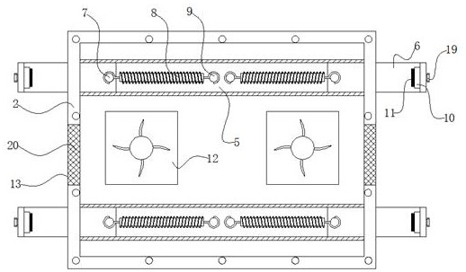
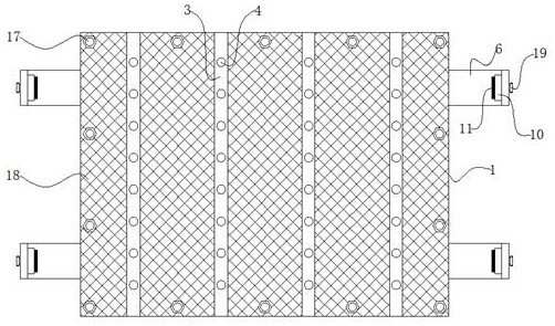
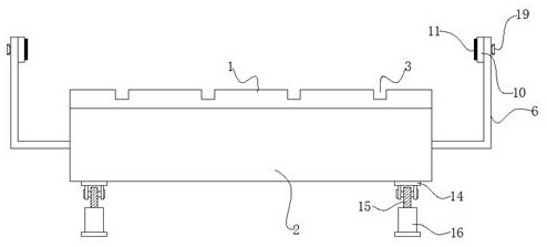
[0020] Such as Figure 1-3 As shown, the invention discloses a heat dissipation device for computer equipment used for software development, including a cover plate 1 and a base 2, the cover plate 1 is detachably installed on the top end of the base 2, and the cover plate 1 is evenly distributed There are a plurality of gap-shaped heat dissipation strips 3, and a plurality of heat dissipation through holes 4 are evenly distributed on the bottom wall of each opened heat dissipation strip 3, and the front and r...


PUM


Abstract

The invention discloses a heat dissipation device of computer equipment for software development. The device comprises a cover plate, the cover plate is detachably mounted at the top opening end of the base; a plurality of notch-shaped heat dissipation strip grooves are uniformly formed in the cover plate; a plurality of heat dissipation through holes are uniformly formed in the bottom wall of each formed heat dissipation strip groove; the front side and the rear side of an inner cavity of the base are each provided with a telescopic rail of an integrated structure. L-shaped telescopic platesare slidably inserted into the two ends of the telescopic rail on each side respectively, movable traction columns fixedly connected with the ends, inserted into the plates, of the L-shaped telescopicplates are connected with the positioning columns through tension springs, and rubber abutting blocks are assembled and installed at the ends, extending outwards, of the L-shaped telescopic plates through groove blocks. By the adoption of the technical scheme, the notebook computer radiator is simple in structure and convenient to assemble and install, improves the radiating effect, adapts to stable use of notebook computers of different specifications and sizes, enables the notebook computers to be conveniently moved to different stations for use, and is convenient to operate.

Description

technical field [0001] The invention relates to the technical field of software development auxiliary devices, in particular to a cooling device for computer equipment used for software development. Background technique [0002] Software development is the process of building a software system or a software part of the system according to user requirements. Software development is a system engineering including requirements capture, requirements analysis, design, implementation and testing. In the existing software development technology, most of them use notebook computers for development and design, and the working time period required for development and design is long. Usually, in order to make the service life of the notebook computer longer, it will be used with a cooling device. The existing cooling device has a single structure , the heat dissipation performance is poor, and it is often just to place the notebook computer on it, but it cannot be adapted to the fixed...

Claims


Application Information

Patent Timeline
Patent Type & Authority Applications(China)
IPC IPC(8): G06F1/20
CPCG06F1/203
Inventor 陈敏
Owner 安徽华睿信息技术有限公司
Learn More