High-reliability optical fiber composite insulator and preparation method thereof
A fiber composite and reliability technology, which is applied in the direction of insulators, fiber mechanical structures, electrical components, etc., can solve problems such as affecting life, fiber breakage, and failure, and achieves improved reliability, high-voltage resistance, and good electrical insulation. Effect
- Summary
- Abstract
- Description
- Claims
- Application Information
AI Technical Summary
Problems solved by technology
Method used
Image
Examples
Embodiment 1
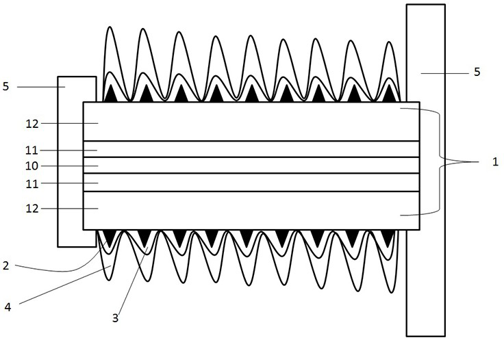
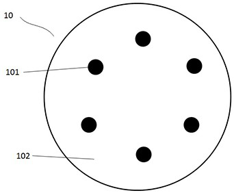
[0028] Example 1, please combine figure 1 with figure 2 As shown, the high-reliability optical fiber composite insulator involved in this embodiment includes a core rod 1, a skeleton 2, a first heat insulating layer 3, an umbrella shed 4 and fittings 5, and the core rod 1 includes an optical fiber cured body 10, a second heat insulating layer 11 and the mandrel body layer 12, the optical fiber cured body 10 is an epoxy resin rod, and the epoxy resin rod can be provided with 2 to 20 axially arranged optical fibers 101. In this embodiment, there are 6 optical fibers, and the 6 optical fibers are mutually The gaps between the optical fibers are filled with epoxy resin 102 . The optical fiber 101 has a core + cladding structure, wherein the core diameter is ≥ 3 mm, the outer diameter of the optical fiber 101 is ≥ 5 mm, and the refractive index n1 of the core and the refractive index n2 of the cladding need to meet: n1-n2 ≥ 0.6, the optical fiber 101 Allowable tensile strength ≥...
Embodiment 2
[0036] Embodiment 2, the structure of the high-reliability optical fiber composite insulator is the same as that of Embodiment 1, and its preparation method is as follows:
[0037] S1. Arrange 6 optical fibers 101 in the first mold, fill the epoxy resin 102 isolating the optical fibers 101 between the optical fibers 101 and cure to obtain the optical fiber cured body 10, after completion, the epoxy resin 102 is coated on the outside of all the optical fibers 101, The optical fiber 101 is arranged along the axial direction of the optical fiber cured body 10;
[0038] S2. Coating and curing the second heat insulating layer 11 made of glass fiber and silicate on the outside of the fiber cured body 10 through the second mold. The mass ratio of glass fiber to silicate is 1:1~2, and the fiber is cured The cross section of the body 10 is at the center of the cross section of the second heat insulating layer 11;
[0039] S3. Cover and solidify the mandrel body layer 12 outside the se...
Embodiment 3
[0043] Embodiment 3, the structure of the high-reliability optical fiber composite insulator is the same as that of Embodiment 1, and its preparation method is as follows:
[0044] S1. Arrange 6 optical fibers 101 in the first mold, fill the epoxy resin 102 isolating the optical fibers 101 between the optical fibers 101 and cure to obtain the optical fiber cured body 10, after completion, the epoxy resin 102 is coated on the outside of all the optical fibers 101, The optical fiber 101 is arranged along the axial direction of the optical fiber cured body 10;
[0045] S2. Coating and curing the second heat insulating layer 11 made of glass fiber and silicate on the outside of the fiber cured body 10 through the second mold. The mass ratio of glass fiber to silicate is 1:1~2, and the fiber is cured The cross section of the body 10 is at the center of the cross section of the second heat insulating layer 11;
[0046] S3. Cover and solidify the mandrel body layer 12 outside the se...
PUM
| Property | Measurement | Unit |
|---|---|---|
| diameter | aaaaa | aaaaa |
Abstract
Description
Claims
Application Information
 - R&D
- Intellectual Property
- Life Sciences
- Materials
- Tech Scout
- Unparalleled Data Quality
- Higher Quality Content
- 60% Fewer Hallucinations
Browse by: Latest US Patents, China's latest patents, Technical Efficacy Thesaurus, Application Domain, Technology Topic, Popular Technical Reports.
© 2025 PatSnap. All rights reserved.Legal|Privacy policy|Modern Slavery Act Transparency Statement|Sitemap|About US| Contact US: help@patsnap.com


