Control method for reducing output ripples of full-bridge LLC converter at intervals

A technology of output ripple and control method, applied in the direction of irreversible DC power input conversion to AC power output, AC power input conversion to DC power output, DC power input conversion to DC power output, etc., can solve the output voltage ripple Wave excess, back and forth jitter, high cost and other problems, to reduce design pressure, reduce the effect of output ripple

Inactive Publication Date: 2020-10-16
SHIJIAZHUANG TONHE ELECTRONICS TECH CO LTD
View PDF15 Cites 2 Cited by
  • Summary
  • Abstract
  • Description
  • Claims
  • Application Information

AI Technical Summary

Problems solved by technology

[0002] Electric vehicles have been booming in recent years and have gradually entered our lives, and their types have become diverse. Correspondingly, the current range of output voltage requirements for electric vehicle chargers has become wider and wider, but it has also brought Here comes a problem, since the input range is generally unchanged, an overly wide output voltage range will cause the LLC of the charging pile to work intermittently when the input is at the high end and the output is at the low end, so that the output voltage will change with the The charging and discharging of the output electrolytic capacitor jitters back and forth, especially at light load, the power supply works in an intermittent state, which makes the output voltage ripple exceed the requirements of the technical index. In this case, according to the current general method, it will be The value of large output inductance and output electrolysis can meet the needs of the design, but with the different degrees of intermittent, the design requirements for output inductance and electrolysis are also different, often through the over-design of the output inductance and electrolysis to meet the needs technical indicators, resulting in high cost and waste

Method used


Image

  • Control method for reducing output ripples of full-bridge LLC converter at intervals

Examples


Embodiment Construction

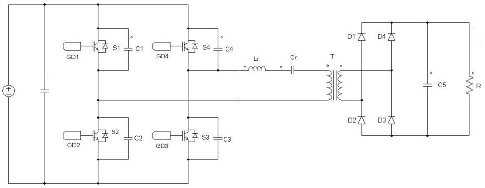
[0010] The technical solutions of the present invention will be further specifically described below through embodiments and in conjunction with the accompanying drawings.

[0011] Usually, the LLC converter relies on simple PI control to realize the operation of various loads. Under light load conditions, the LLC converter will work in a gap state (working for a period of time, resting for a period of time), and the intermittent frequency is much lower than the switching frequency. It will cause the output filter to be unable to filter out the ripple of the output voltage in the intermittent state, making it difficult for the output voltage ripple to meet the technical indicators. Using the method of the present invention allows the LLC converter to work in the phase-shift control mode at light load, the jitter frequency of the output voltage is the switching frequency, and the output filter circuit can well filter out the phase-shift control mode at light load. Output ripple...


PUM


Abstract

The invention discloses a control method for reducing output ripples of a full-bridge LLC converter at intervals. The method and the circuit are suitable for a full-bridge LLC converter circuit. The method comprises the following steps: dividing four primary switching tubes into two groups according to a mode of being connected with an input power supply in series, wherein the first group comprises a first switching tube and a second switching tube which are connected in series, the second group comprises a third switching tube and a fourth switching tube which are connected in series, and a wave sending mode adopted by the method is as follows: the LLC converter is set to have a fixed frequency adjustment range to control a first switching tube and a second switching tube in the switchingtubes to drive waveform complementation and control the third switching tube and the fourth switching tube to drive waveform complementation, through phase shift control, the overlapping time of driving waveforms of the first switching tube and the third switching tube is determined according to the output value of PI adjustment, the longer the overlapping time is, the higher the gain of the LLCconverter is, and the stronger the loading capacity is, so that the LLC converter has no intermittent state, the output capacitor does not have low-frequency charging and discharging, and the output voltage ripple can reach a very small output voltage ripple.

Description

technical field [0001] The invention relates to the field of power conversion, in particular to a control method for reducing the intermittent output ripple of a full-bridge LLC converter. Background technique [0002] Electric vehicles have been booming in recent years and have gradually entered our lives, and their types have become diverse. Correspondingly, the current range of output voltage requirements for electric vehicle chargers has become wider and wider, but it has also brought Here comes a problem, since the input range is generally unchanged, an overly wide output voltage range will cause the LLC of the charging pile to work intermittently when the input is at the high end and the output is at the low end, so that the output voltage will change with the The charging and discharging of the output electrolytic capacitor jitters back and forth, especially at light load, the power supply works in an intermittent state, which makes the output voltage ripple exceed th...

Claims


Application Information

Patent Timeline
Patent Type & Authority Applications(China)
IPC IPC(8): H02M3/335H02M7/48H02M1/14
CPCH02M3/33569H02M7/48H02M1/14H02M7/4815Y02B70/10
Inventor 田超杨飞蒋东岩乔凯明彭玉成赵伟焦凌云徐奥运牛江飞王兴
Owner SHIJIAZHUANG TONHE ELECTRONICS TECH CO LTD
Why Eureka
Try Eureka