Dc/dc conversion apparatus

a conversion apparatus and converter technology, applied in the direction of electric variable regulation, process and machine control, instruments, etc., can solve the problems of unfavorable production and use, and complicated control of parameters, so as to achieve stable adjustment in a wide range, less variation ratio of output energy, and less output ripple

Active Publication Date: 2017-03-30
MURATA MFG CO LTD
View PDF1 Cites 8 Cited by
  • Summary
  • Abstract
  • Description
  • Claims
  • Application Information

AI Technical Summary

Benefits of technology

[0031]According to various preferred embodiments of the present invention, a stable adjustment in a wide range is obtained by adjusting a length of time of opening the electrical connection between the oscillation circuit and the DC voltage source and a length of time of applying a forward voltage or reverse voltage to the oscillation circuit.
[0032]Further, according to various preferred embodiments of the present invention, the gain is able to be adjusted such that a switching frequency of the converter will not have a larger change. While the gain varies, a variation ratio of the output energy is less and an output ripple is smaller.
[0033]Furthermore, according to various preferred embodiments of the present invention, a switching loss of the switch element when it is turned on is able to be reduced and furthermore the switch element is allowed to realize a zero voltage switch (ZVS).

Problems solved by technology

Parameters involved in changing the gain in the above manner are numerous, and control of the parameters is quite complicated.
The oscillation between the DC voltage source V1 and the oscillation circuit 20 and a resistance present on a current path of the oscillation circuit 20 will result in an unnecessary loss.
A resistance present on the current path of the oscillation circuit 20 will result in an unnecessary loss.
On the other hand, in the DC / DC conversion apparatus that employs a LLC full-bridge circuit, there is also a problem of a loss of a switch (i.e., MOSFET, etc.).
At the same time, a variation ratio of a voltage and a current of the switch during the turn-on and the turn-off is restricted by the resonance process, which also significantly decreases the noise of the switch.
However, in the DC / DC conversion apparatus 100 as shown in FIG. 6, when the load becomes lighter, increasing the switching frequency of the switch will result in an increased switching loss.

Method used


Image

  • Dc/dc conversion apparatus
  • Dc/dc conversion apparatus
  • Dc/dc conversion apparatus

Examples


first preferred embodiment

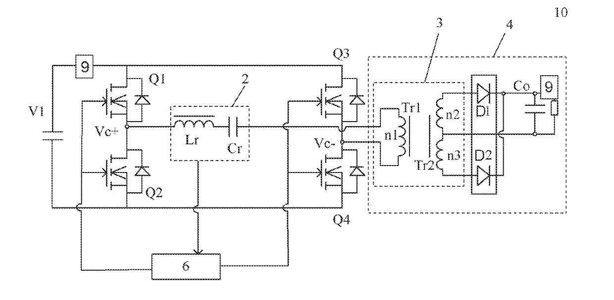
[0043]A DC / DC conversion apparatus according to a first preferred embodiment of the present invention will be described below with reference to FIG. 1.

[0044]FIG. 1 is a block diagram illustrating a circuit structure of a DC / DC conversion apparatus 10 according to a first preferred embodiment of the present invention. As shown in FIG. 1, the DC / DC conversion apparatus 10 includes a DC voltage source V1 that outputs a DC power supply voltage Vin; an oscillation circuit 2 being electrically connected to the DC voltage source V1; a plurality of switch elements Q1˜Q4; a switch controller 6, which closes or opens an electrical connection between the DC voltage source V1 and the oscillation circuit 2 by switching turn-on and turn-off of the plurality of switch elements Q1˜Q4, and switches a direction of a voltage applied to the oscillation circuit 2 between a first direction and a second direction; a transformation circuit 4 that outputs a current generated in the oscillation circuit 2 and...

second preferred embodiment

[0092]In a second preferred embodiment of the present invention, when the output voltage Vout varies dramatically, the process of commonly turning on the switches Q2 and Q3 may be removed.

[0093]For example, assume a stable output voltage Vout of the DC / DC conversion apparatus in the symmetric operation status is about 12 V, when the output voltage Vout suddenly increases to about 15 V, the DC / DC conversion apparatus may be directly switched from a full-bridge operation status to a half-bridge operation status. In other words, the switch element Q1 and the switch element Q4 are turned on at the same time and the switch element Q2 and the switch element Q3 are turned off at the same time under the control of the switch controller, such that the voltage of the oscillation circuit firstly is in the first direction, then the electrical connection between the oscillation circuit and the DC voltage source is opened, and next the direction of the voltage applied on the oscillation circuit r...


PUM


Abstract

A DC/DC conversion apparatus includes a DC voltage source, an oscillation circuit being electrically connected to the DC voltage source, a plurality of switch elements, a switch controller, which closes or opens electrical connection between the DC voltage source and the oscillation circuit by switching turn-on and turn-off of the plurality of switch elements, and switches a direction of a voltage applied on the oscillation circuit between a first direction and a second direction, a transformation circuit, a detector to detect one or more parameter values of an input voltage and input current of the DC voltage source and an output voltage and output current to the transformation circuit, wherein when the parameter values vary, the switch controller adjusts a length of time in which the voltage applied on the oscillation circuit is in one of the first direction and the second direction, such that the output voltage and/or output current returns to an initial value.

Description

CROSS REFERENCE TO RELATED APPLICATIONS[0001]This application claims the benefit of priority to Chinese Patent Application No. 201510640591.3 filed Sep. 30, 2015. The entire contents of this application is hereby incorporated herein by reference.BACKGROUND OF THE INVENTION[0002]1. Field of the Invention[0003]The present invention relates to a DC / DC conversion apparatus that includes a LLC full-bridge circuit.[0004]2. Description of the Related Art[0005]In the prior art, a switch power supply is one power supply that utilizes a modern power electronic technology to control a ratio of a turn-on time and a turn-off time of a switch and maintain a stable output voltage, in which a DC / DC conversion apparatus, i.e., direct current-direct current conversion circuit, is a voltage transformer that effectively converts a DC input voltage into a fixed DC output voltage. Generally, the DC / DC conversion apparatus is divided into three types: a boost DC / DC transformer, a buck DC / DC transformer, a...

Claims


Application Information

Patent Timeline
Patent Type & Authority Applications(United States)
IPC IPC(8): H02M3/335H02M1/15
CPCH02M1/15H02M3/33507H02M3/3376Y02B70/10H02M1/0058H02M3/33573H02M3/01
Inventor DAI, JIALECAO, YUWANG, KEZHI
Owner MURATA MFG CO LTD
Why Eureka
Try Eureka