Switching regulator and operation control method thereof

a technology of switching regulator and operation control method, which is applied in the direction of power conversion systems, dc-dc conversion, instruments, etc., can solve the problems of increasing the electric power consumption of the switching regulator itself in proportion to the switching frequency, increasing the ripple of the output voltage, and increasing the fall speed of the error voltage opout, so as to improve the efficiency of vfm control mode, reduce the ripple of the output voltage, and simple circuit configuration

Active Publication Date: 2014-09-09
NISSHINBO MICRO DEVICES INC
View PDF31 Cites 7 Cited by
  • Summary
  • Abstract
  • Description
  • Claims
  • Application Information

AI Technical Summary

Benefits of technology

[0018]An object of the present invention is to provide a solution for the above problems, and in particular, an object of the present invention is to provide a switching regulator and its operation control method capable of equaling the maximum switching frequency in the VFM control mode to the switching frequency in the PWM control mode by a simple circuit configuration, making the ripple of the output voltage smaller, and improving an efficiency in the VFM control mode.

Problems solved by technology

The electric power consumption of the switching regulator itself increases in proportion to a switching frequency.
However, because noise occurring from the switching regulator greatly affects a peripheral device, it is necessary to give consideration to such noise.
Even in the VFM control mode, a maximum switching frequency in the VFM control is inconsistent; therefore in a case where the switching regulator is turned on and energy is supplied to an inductor before an inductor current becomes zero, there is a problem in that the ripple of the output voltage further becomes large.
In addition, the smaller the output current iout is, the faster the output voltage Vout rises; therefore a fall speed of the error voltage opout becomes fast, and the duration in which the switching transistor M101 is on becomes short.
However, the conventional switching regulator as described in FIG. 8 is not capable of controlling a maximum switching frequency in the VFM control mode, and as described as a waveform diagram of FIG. 9, depending on a setting of a circuit parameter, equal to or more than 2 times of switching is performed in one period of a switching cycle in the PWM control mode.
Therefore, the maximum switching frequency in the VFM control mode becomes larger than a switching frequency in the PWM control mode, and there is a problem such that it is necessary to make consideration for noise which is equal to or more than the switching frequency in the PWM control mode.
In addition, there is a problem such that a ripple of the output voltage Vout becomes large, because the switching transistor M101 is turned on and energy is supplied to the inductor L101 before the inductor current iL becomes zero.
However, as an oscillator always operates, a consumption current increases and this prevents the efficiency from improving.
And additionally, a step-down switching regulator of a variable frequency type has a problem such that it is not capable of setting the maximum switching frequency in the VFM control mode as well as the switching regulator of FIG. 8.

Method used


Image

  • Switching regulator and operation control method thereof
  • Switching regulator and operation control method thereof
  • Switching regulator and operation control method thereof

Examples


embodiment

[Embodiment]

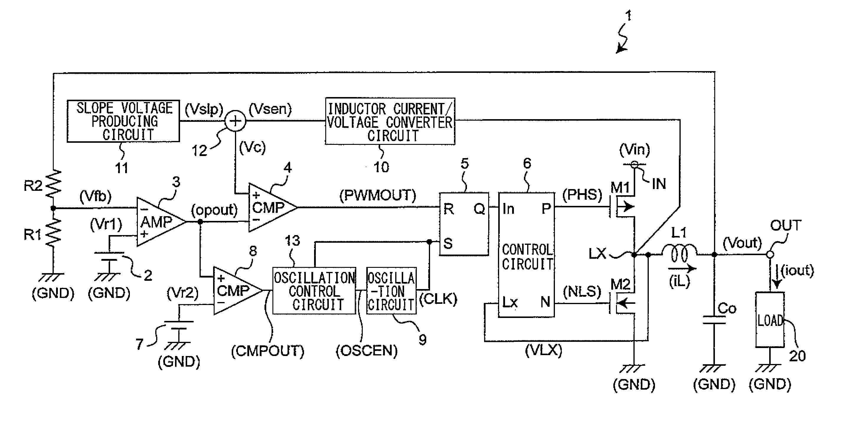
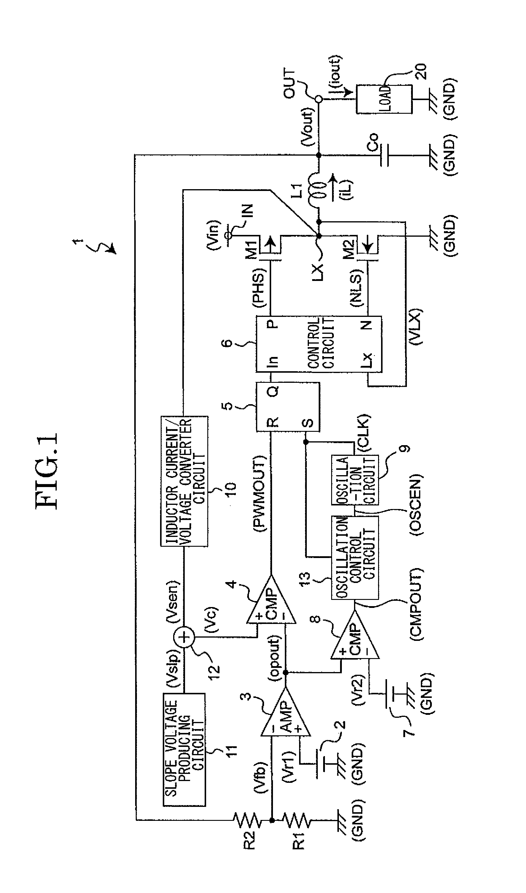
[0031]FIG. 1 is a diagram illustrating a circuit example of a switching regulator in the embodiment of the present invention.

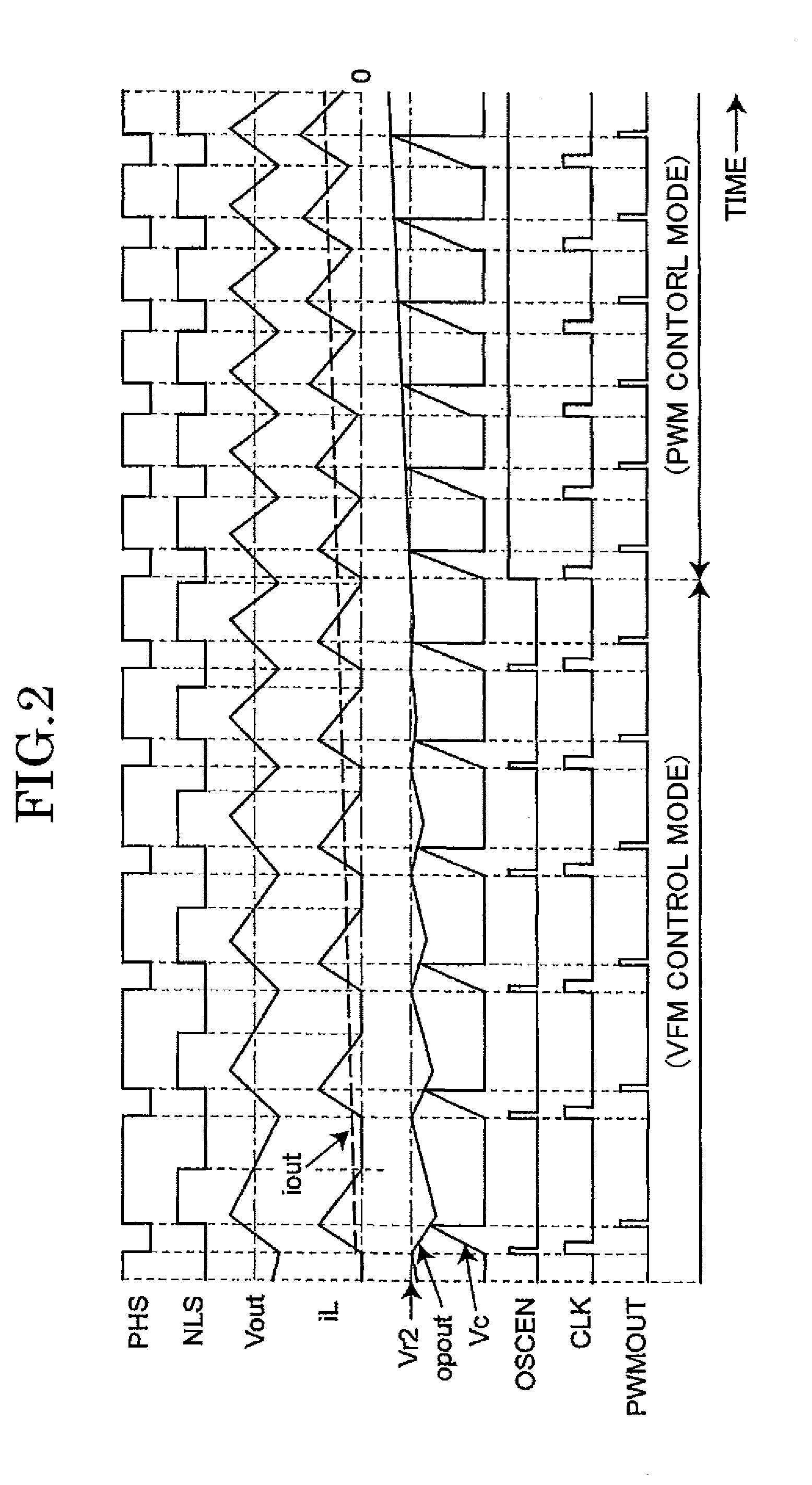
[0032]In FIG. 1, a switching regulator 1 functions as a current mode controlled switching regulator of a synchronous rectification type which steps down an input voltage Vin inputted to an input terminal IN to a predetermined constant voltage and outputs as an output voltage Vout from an output terminal OUT to a load 20. And the switching regulator 1 performs the above step-down operation by automatically performing a switching of a PWM control and a VFM control based on an output current iout outputted from an output terminal OUT.

[0033]The switching regulator 1 includes a switching transistor M1 of a PMOS transistor and a synchronous rectification transistor M2 of an NMOS transistor.

[0034]In addition, the switching regulator 1 includes a first reference voltage generating circuit 2 which generates and outputs a predetermined first reference voltag...


PUM


Abstract

A non-isolated type switching regulator having an inductor includes: a switch element; a rectification element; an error amplifying circuit section amplifying a voltage difference between a feedback voltage and a first reference voltage and outputting as an error voltage; a first voltage comparison circuit section performing a voltage comparison of a ramp voltage which performs a voltage change set beforehand with the error voltage to be synchronized with the switching of the switch element and producing and outputting a first comparison signal; a second voltage comparison circuit performing a voltage comparison of the error voltage with a second reference voltage and producing and outputting a second comparison signal; an oscillation circuit section starting an oscillation based on the second comparison signal and producing and outputting a clock signal; and a control circuit section performing a switching control of the switch element based on the clock signal and the first comparison signal.

Description

TECHNICAL FIELD[0001]The present invention relates to a switching regulator which functions as a DC-DC converter, and in particular, relates to a switching regulator which has a PWM (Pulse Width Modulation) control mode and a VFM (Variable Frequency Modulation) control mode and switches the control modes based on, for example, a state of an output current.BACKGROUND ART[0002]In recent years, power saving of an electronic device has been demanded in consideration of environmental issues, and the trend to save power has been particularly prominent in an electronic device driven by a battery. Generally, in order to achieve such power saving, reducing the electric power consumed by the electronic device, and improving the efficiency of a power circuit itself and suppressing wasteful electric power consumption are important. A non-isolated switching regulator using an inductor is widely used as a high-efficiency power circuit used for a small electronic device.[0003]There are two major c...

Claims


Application Information

Patent Timeline
Patent Type & Authority Patents(United States)
IPC IPC(8): H02M3/156H02M3/158
CPCH02M3/158H02M3/156H02M3/155
Inventor MICHISHITA, YUUSUKESHIMIZU, SHINYA
Owner NISSHINBO MICRO DEVICES INC
Why Eureka
Try Eureka