Downward pressing structure special for building steel bar cutter

A technology for building steel bars and cutting machines, which is applied in the field of steel bar cutting machine accessories, can solve the problems of labor-intensive oil injection, increased friction, and reduced work efficiency.

Inactive Publication Date: 2020-10-20
赖路玉
View PDF10 Cites 2 Cited by
  • Summary
  • Abstract
  • Description
  • Claims
  • Application Information

AI Technical Summary

Problems solved by technology

[0003] In the actual use of the special pressing structure of the construction steel bar cutting machine, guide rods are installed at both ends of the pressing plate at the bottom for guiding during the pressing down, and the guide rods are easy to lose lubrication in long-term use, result

Method used


Image

  • Downward pressing structure special for building steel bar cutter
  • Downward pressing structure special for building steel bar cutter
  • Downward pressing structure special for building steel bar cutter

Examples


Embodiment 1

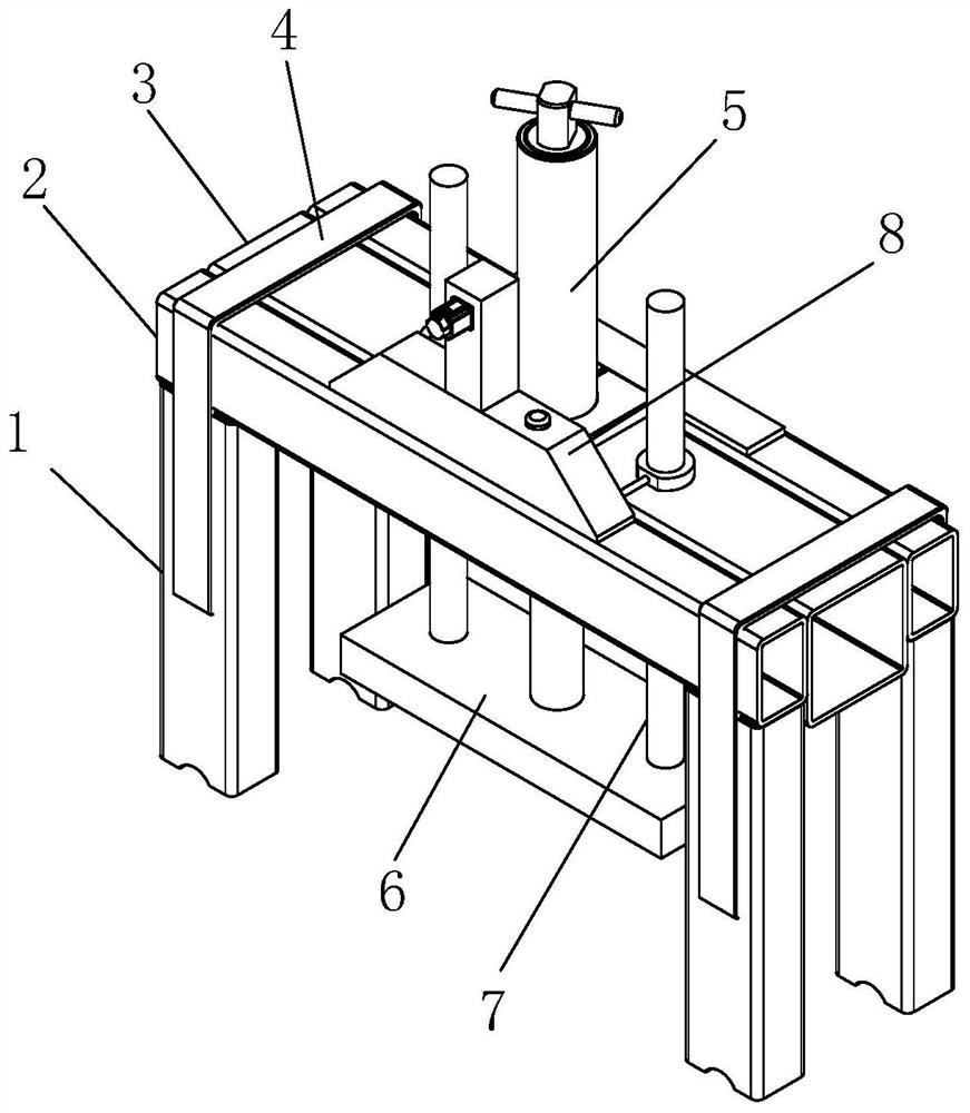
[0029] see figure 1 , the present invention provides a special press-down structure for a building steel bar cutting machine through improvement, including pillars 1, four sets of pillars 1 are provided, and the front and rear ends of the top of the four sets of pillars 1 are fixed with ejector rods 2, and the inner sides of the ejector rods 2 Fixed with the fixed plate 3, the top of the fixed plate 3 is respectively fixed with the pillar 1 and the ejector rod 2 through the guard 4, and the middle part of the top of the fixed plate 3 is installed with a hydraulic cylinder 5. 6. A guide rod 7 is fixed vertically at the left and right ends of the top, and the top of the guide rod 7 runs through the fixed plate 3, and a lubricating device 8 is provided at the front end of the top of the ejector rod 2 .

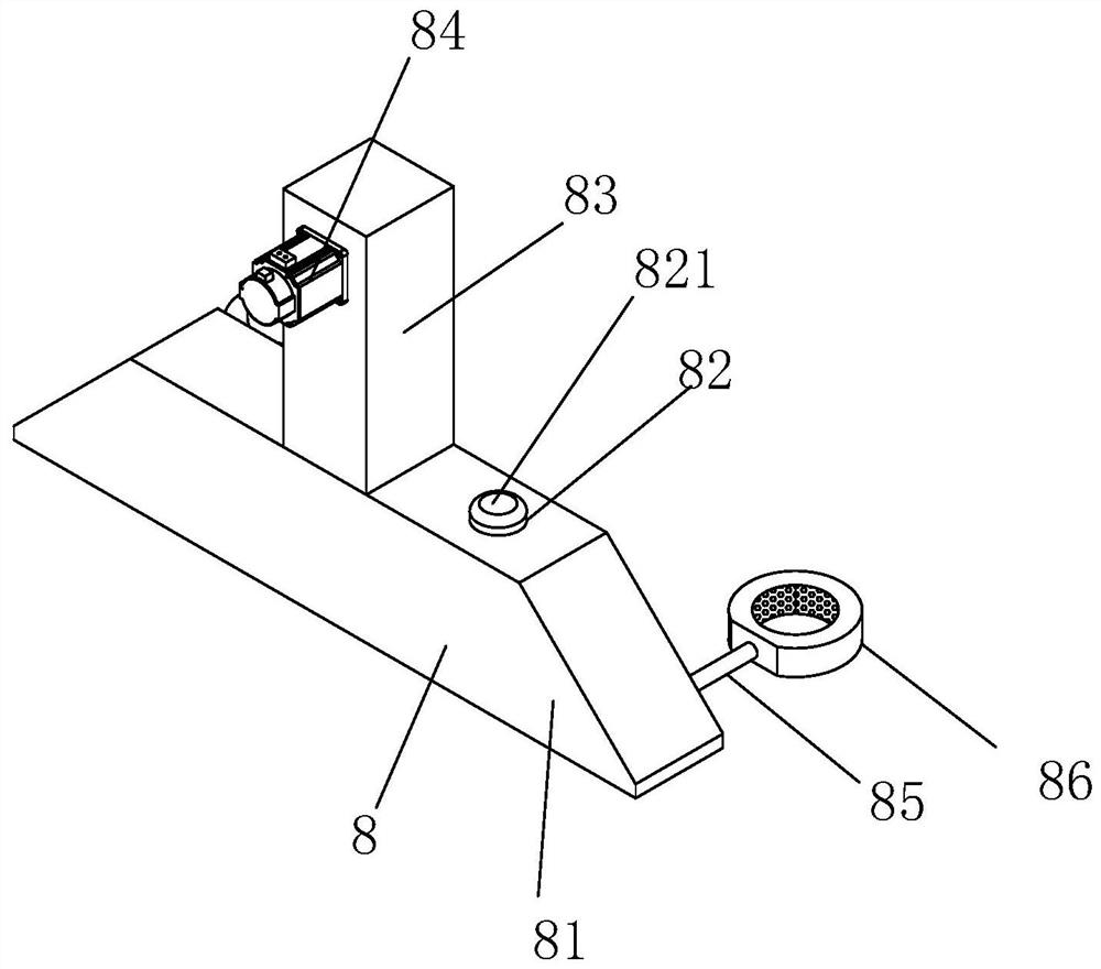
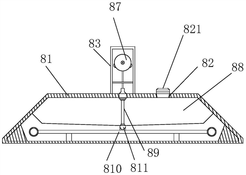
[0030] see figure 2 and image 3 , the present invention provides a special pressing structure for a building steel bar cutting machine through improvement. The lubricating de...

Embodiment 2

[0035] The present invention provides a special pressing structure for building steel bar cutting machine through improvement. The housing 81 is trapezoidal, and the back of the housing 81 is provided with a sealing cover. The sealing cover and the housing 81 are fixed by bolts, which is convenient for users to Internal inspection and maintenance are carried out; the oil pipe 85 is flexible, which is convenient for oil filling and has a long service life; both ends of the oil pipe 85 are bonded with a layer of silica gel, which effectively improves the sealing performance and prevents leakage.

[0036] The present invention provides a special pressing structure for a building steel bar cutting machine through improvement, and its working principle is as follows;

[0037] First, when the pressing structure needs to be used, the pressing structure is first installed on the steel bar cutting machine, and then the user connects the hydraulic cylinder 5 with the external hydraulic e...


PUM


Abstract

The invention discloses a downward pressing structure special for a building steel bar cutter. The downward pressing structure comprises a supporting column, an ejector rod, a fixing plate, a protecting piece, a hydraulic cylinder, a pressing plate, a guide rod and a lubricating device; the lubricating device is installed at the top of the ejector rod, an oil bin is installed inside the lubricating device and can store lubricating oil, the lubricating oil is discharged through a branch pipe at the bottom and then enters a fixing sleeve through an oil pipe, namely, the position of the guide rodcan be lubricated, the effect is good, and the lubricating efficiency is high. A reciprocating mechanism is installed in the lubricating device and controlled by an independent driving motor, so thata fixing plug at the bottom is moved out of a bottom outlet of the oil bin, the lubricating oil can stably flow into the branch pipe at the bottom, excessive manual operation is not needed, and the automation effect is good; the oil absorption cotton is installed in the fixing sleeve and absorbs the lubricating oil discharged from the oil pipe, and then the lubricating oil seeps out through a permeation ring on the inner side of the fixing sleeve, so that the contact position of the guide rod and the fixing plate is continuously and stably lubricated.

Description

technical field [0001] The invention relates to the relevant field of steel bar cutting machine accessories, in particular to a special pressing structure for a building steel bar cutting machine. Background technique [0002] Construction steel bars refer to various steel bars, steel wires and other steel bars used in reinforced concrete. According to the steel types, they are divided into: non-alloy steel bars, low-alloy steel bars, and alloy steel bars; when building bars are used, special cutting machines are required. It cuts. The steel bar cutting machine is a tool used to cut steel bars. There are fully automatic steel bar cutting machines and semi-automatic steel bar cutting machines. On the automatic cutting machine, a special pressing structure needs to be installed to make the knife head Press down to cut off the steel bar. [0003] In the actual use of the special pressing structure of the construction steel bar cutting machine, guide rods are installed at both ...

Claims


Application Information

Patent Timeline
IPC IPC(8): B21F11/00
CPCB21F11/00
Inventor 赖路玉
Owner 赖路玉
Why Eureka
Try Eureka