Eureka AIR delivers breakthrough ideas for toughest innovation challenges, trusted by R&D personnel around the world.

Snap spring disassembling equipment

A circlip and equipment technology, applied in the field of dismantling equipment, can solve the problems of inability to adapt to modern and industrialized production, low work efficiency, and low output

Inactive Publication Date: 2020-10-20
上海冉本智能科技有限公司
View PDF5 Cites 0 Cited by
  • Summary
  • Abstract
  • Description
  • Claims
  • Application Information

AI Technical Summary

Problems solved by technology

[0002] At present, in the dismantling process of powder metallurgy brake pads, it is usually done manually. This operation method is slow in dismantling speed, low in work efficiency, low in output, and unable to adapt to modern and industrialized production. Therefore, in order to speed up the card The dismantling speed of the spring, we have studied the dismantling equipment of the spring

Method used


Image

  • Snap spring disassembling equipment

Examples


Embodiment Construction

[0013] The present invention will be further described below in conjunction with the accompanying drawings and embodiments.

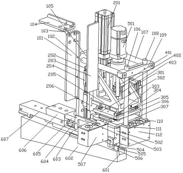
[0014] Such as figure 1 As shown, a circlip dismantling equipment includes a supporting device, a lifting device, a positioning device, a centering device, a dismantling device, and a material device; the material device is arranged under the supporting device, and the lifting device, the positioning device , centering device and dismantling device are all set inside the supporting device.

[0015] Described supporting device is by supporting plate 105, is arranged on two connecting columns on supporting plate 105, is respectively the first connecting column 102, the second connecting column 107; One connects the connecting block 109 of two connecting columns, two are fixed on The supporting columns on the connection block 109 are respectively the first supporting column 106 and the second supporting column 108; and a detection device 112 fixed on the ...


PUM


Abstract

The invention discloses snap spring disassembling equipment which comprises a supporting device, a lifting device, a positioning device, a centering device, a disassembling device and a material device. The operation of the whole equipment is supported by the supporting device, and the positioning device is upwards supported by a triangular support of the lifting device; the positioning device isused for achieving downward moving positioning of the snap spring, the centering device is used for achieving displacement fine adjustment in the disassembling process of the snap spring, and the snapspring is kept in the center of the positioning device all the time. The disassembling device is used for disassembling the snap spring; temporary storage and transportation of the disassembled snapsprings are achieved through the material device, and materials can be conveniently stored in the waste box in time. The whole process is achieved through operation of the air cylinder and the motor and is basically completed in a semi-automatic mode, only one person needs to conduct corresponding operation beside according to signals of the detector, the disassembling speed of the snap spring isgreatly increased, the working efficiency is improved, and then the production yield of brake linings is increased.

Description

technical field [0001] The invention relates to a dismantling device, in particular to a dismantling device for a circlip, which is applied to the production and processing technology industry of powder metallurgy brake discs. Background technique [0002] At present, in the dismantling process of powder metallurgy brake pads, it is usually done manually. This operation method is slow in dismantling speed, low in work efficiency, low in output, and unable to adapt to modern and industrialized production. Therefore, in order to speed up the card The dismantling speed of the circlip, we have studied the dismantling equipment of the circlip. Contents of the invention [0003] In order to solve the above problems, the present invention provides a circlip dismantling device, which can effectively increase the dismantling speed of the circlip, improve work efficiency, and further increase the production output of brake pads. [0004] For realizing above-mentioned object, the te...

Claims


Application Information

Patent Timeline
Patent Type & Authority Applications(China)
IPC IPC(8): B23P19/00
CPCB23P19/00
Inventor 张亮
Owner 上海冉本智能科技有限公司
Why Eureka
Eureka Blog
Learn More