Filter debugging method, device, electronic device and readable storage medium

A debugging method and filter technology, applied in the field of reinforcement learning, can solve the problems of high labor cost and time cost, low filter debugging efficiency, etc., and achieve the effect of improving debugging efficiency

Active Publication Date: 2022-04-29
BEIJING BAIDU NETCOM SCI & TECH CO LTD
View PDF9 Cites 0 Cited by
  • Summary
  • Abstract
  • Description
  • Claims
  • Application Information

AI Technical Summary

Problems solved by technology

[0002] With the advent of the 5G communication era, the demand for filters (such as ceramic dielectric filters) is increasing rapidly. In the production process of filters, in order to ensure the performance of the filters, each filter needs repeated debugging by skilled workers. Need to consume high labor cost and time cost, which leads to low filter debugging efficiency

Method used


Image

  • Filter debugging method, device, electronic device and readable storage medium
  • Filter debugging method, device, electronic device and readable storage medium
  • Filter debugging method, device, electronic device and readable storage medium

Examples


no. 1 example

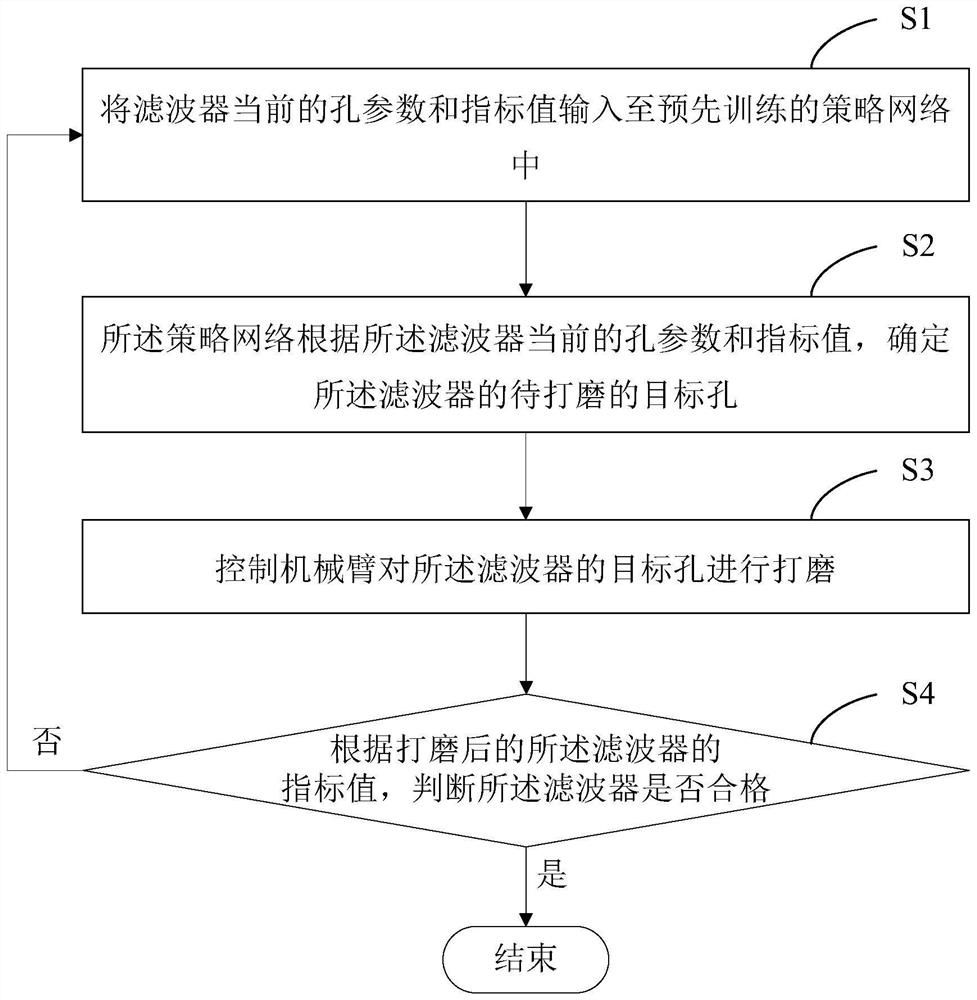
[0030] like figure 1 As shown, the present application provides a filter debugging method, including the following steps:

[0031] Step S1: Input the current hole parameters and index values ​​of the filter into the pre-trained policy network;

[0032] Step S2: The policy network determines the target hole to be polished of the filter according to the current hole parameters and index values ​​of the filter;

[0033] Step S3: controlling the mechanical arm to polish the target hole of the filter;

[0034] Step S4: According to the index value of the polished filter, judge whether the filter is qualified, if the filter is qualified, then end; if the filter is not qualified, execute the steps S1 to all Repeat step S4 until the filter is qualified.

[0035] In this application, the filter may include a ceramic dielectric filter or other filters. The aperture parameters of the filter may include aperture depth and aperture, and the filter index may include at least one of cent...

no. 2 example

[0076] like Figure 5 As shown, the present application provides a filter debugging device 300, including an input module 301, a control module 302, a judgment module 303 and a pre-trained policy network 304;

[0077] The input module 301 is used to input the current hole parameters and index values ​​of the filter into the strategy network 304;

[0078] The strategy network 304 is used to determine the target hole to be polished of the filter according to the current hole parameters and index values ​​of the filter;

[0079] The control module 302 is used to control the mechanical arm to grind the target hole of the filter;

[0080] The judging module 303 is used to judge whether the filter is qualified according to the index value of the filter after polishing, if the filter is qualified, then end; if the filter is unqualified, trigger the input module 301, strategy Network 304 and control module 302 process until the filter is qualified.

[0081] Optionally, the input mo...


PUM


Abstract

The application discloses a filter debugging method, device, electronic equipment and readable storage medium, and relates to the technical fields of filter intelligent debugging and deep learning. Wherein, the filter debugging method includes: step S1: input the current hole parameters and index values ​​of the filter into the pre-trained strategy network; step S2: the strategy network according to the current hole parameters and index values ​​of the filter, Determine the target hole of the filter to be polished; step S3: control the mechanical arm to polish the target hole of the filter; step S4: judge whether the filter is Qualified, if the filter is qualified, then end; if the filter is not qualified, execute step S1 to step S4 in a loop until the filter is qualified. The application realizes the intelligent debugging of the filter, replaces manual debugging of the filter, improves the efficiency of filter debugging, and solves the problems existing in the prior art.

Description

technical field [0001] The present application relates to reinforcement learning technology, in particular to the technical field of filter intelligent debugging, and in particular to a filter debugging method, device, electronic equipment and readable storage medium. Background technique [0002] With the advent of the 5G communication era, the demand for filters (such as ceramic dielectric filters) is increasing rapidly. In the production process of filters, in order to ensure the performance of the filters, each filter needs repeated debugging by skilled workers. High labor cost and time cost are required, which leads to low filter debugging efficiency. Contents of the invention [0003] The present application provides a filter debugging method, device, electronic equipment and readable storage medium. [0004] According to the first aspect, the present application provides a filter debugging method, including: [0005] Step S1: Input the current hole parameters and ...

Claims


Application Information

Patent Timeline
Patent Type & Authority Patents(China)
IPC IPC(8): B24B5/48G06F30/27
CPCB24B5/48G06F30/27G06F30/17H01P11/007G06F30/367G06F30/373H04L41/16H04L43/028H04W84/02
Inventor 许铭解鑫刘颖齐月震李瑞锋白璐
Owner BEIJING BAIDU NETCOM SCI & TECH CO LTD
Why Eureka
Try Eureka