Robot hand-eye calibration method and device and robot

A calibration method and hand-eye calibration technology, applied in the field of robot calibration, can solve problems such as large manual calibration error

Active Publication Date: 2020-10-20
SHENZHEN HORN AUDIO
View PDF14 Cites 21 Cited by
  • Summary
  • Abstract
  • Description
  • Claims
  • Application Information

AI Technical Summary

Problems solved by technology

[0003] In view of this, the embodiment of the present invention provides a robot hand-eye calibration method, device and robot to solve the problem of large errors in manual calibration

Method used


Image

  • Robot hand-eye calibration method and device and robot
  • Robot hand-eye calibration method and device and robot
  • Robot hand-eye calibration method and device and robot

Examples


Embodiment 1

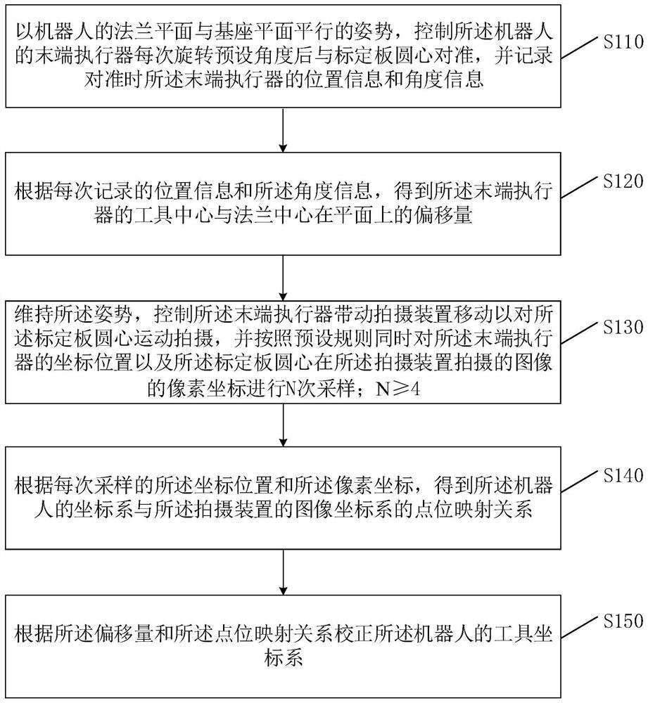
[0046] Such as figure 1 As shown, it is a schematic flow chart of the robot hand-eye calibration method provided by Embodiment 1 of the present invention. This embodiment is applicable to the application scenario of hand-eye calibration for industrial robots and shooting devices. The method can be performed by a robot hand-eye calibration device, which can be a processor, an intelligent terminal, a tablet or a PC, etc.; in this embodiment of the application Taking the robot hand-eye calibration device as the execution subject for illustration, the method specifically includes the following steps:

[0047] S110. With the attitude that the flange plane of the robot is parallel to the base plane, control the end effector of the robot to align with the center of the calibration plate after each rotation of the preset angle, and record the position information of the end effector during alignment and angle information; wherein, the center of the calibration plate is the position o...

Embodiment 2

[0084] Such as Figure 5 Shown is a schematic flow chart of the robot hand-eye calibration method provided by Embodiment 2 of the present invention. On the basis of the first embodiment, this embodiment also provides a process of correcting the tool coordinate system of the robot according to the offset and point-position mapping relationship to grab the workpiece, so as to realize the precise grasping of the workpiece by the robot. The method specifically includes:

[0085] S210. Using the posture of the flange plane of the robot parallel to the base plane, photograph the current workpiece through the photographing device, and obtain the pixel coordinates and the workpiece angle of the image of the current workpiece on the photographing device;

[0086] Since the robot's flange plane is parallel to the base plane, the robot's flange plane is parallel to the robot base plane. At this time, R(X)=180°, R(Y)=0°, and the Z axis is perpendicular to the XY plane, that is, perpendi...

Embodiment 3

[0099] Such as Figure 6 Shown is the robot hand-eye calibration device provided by Embodiment 3 of the present invention. On the basis of Embodiment 1 or 2, the embodiment of the present invention also provides a robot hand-eye calibration device 6, which includes:

[0100] The tool coordinate system calibration module 601 is used to control the end effector of the robot to align with the center of the calibration plate after each rotation of the preset angle with the attitude that the flange plane of the robot is parallel to the base plane, and record the alignment. position information and angle information of the end effector;

[0101] In an implementation example, with the posture that the flange plane of the robot is parallel to the plane of the base, the end effector of the robot is controlled to align with the center of the calibration plate after each rotation of a preset angle, and the end effector of the robot is recorded during the alignment. When the position in...


PUM


Abstract

The invention belongs to the technical field of robot calibration, and provides a robot hand-eye calibration method and device and a robot. The method comprises the steps: controlling an end effectorof the robot to be aligned with the circle center of a calibration plate after rotating for a preset angle each time in a posture that a flange plane of the robot is parallel to a base plane, and recording the position information and angle information of the end effector during alignment; obtaining the offset of the tool center of the end effector and the flange center on the plane; controlling the end effector to drive a shooting device to move so as to shoot the circle center of the calibration plate, and simultaneously sampling the coordinate position of the end effector and the pixel coordinates of the circle center of the calibration plate in the image shot by the shooting device for N times according to a preset rule; obtaining a point location mapping relationship between a coordinate system of the robot and an image coordinate system of a shooting device; and correcting a tool coordinate system of the robot according to the offset and the point location mapping relationship. According to the embodiment of the invention, the problem of large manual calibration error is solved.

Description

technical field [0001] The invention relates to the technical field of robot calibration, in particular to a robot hand-eye calibration method, device and robot. Background technique [0002] In the existing calibration technology of industrial robots and cameras, it is necessary to use specific calibration boards, such as checkerboard calibration boards, dot calibration boards, etc., and the robot must be controlled in a variety of different postures (for 6-axis robots, There are at least four types, but generally for higher calibration accuracy, basically 15-20 postures are used to control the camera to shoot the calibration board. Due to different postures, the images of the calibration board taken by the camera are different. In order to stabilize the image Finding the calibration board in the robot brings a lot of difficulty to image processing and improving the calibration accuracy. To adjust the posture of the robot, manual teaching is required. It takes a lot of tim...

Claims


Application Information

Patent Timeline
Patent Type & Authority Applications(China)
IPC IPC(8): B25J9/16
CPCB25J9/1602B25J9/1697B25J9/1664
Inventor 殷波王仁忠王丽
Owner SHENZHEN HORN AUDIO
Why Eureka
Try Eureka