
Automatic wall surface roughening device and wall surface construction method thereof

A brushing device and automatic technology, which are applied in construction, building structure, processing of building materials, etc., can solve the problems of difficult to control the depth of brushing, unfavorable adhesion between tiles and walls, and easy falling off of tiles.

Inactive Publication Date: 2020-10-20
福建大华建设工程股份有限公司
View PDF7 Cites 3 Cited by
  • Summary
  • Abstract
  • Description
  • Claims
  • Application Information

AI Technical Summary

Problems solved by technology

[0002] With the development of building industrialization, casting walls with aluminum alloy formwork has become an essential process for wall pouring. A typical feature of this process is that the surface of the poured wall is very smooth and flat, and the practicability and aesthetics of this process It is self-evident, however, for some walls that still need to be tiled in the future, an overly smooth wall is not conducive to the bonding between the tiles and the wall. If the smooth wall is not roughened, the tiles are easy to fall off. Therefore, Essential for roughening smooth walls
[0003] At present, there are generally two types of napping equipment, one is powered by machinery, and the other is powered by high-pressure water jets. The first method is mainly through the interaction between the blade and the concrete. The surface of the concrete is formed with grooves. This method is a traditional method. Although it is widely used, it has certain defects, which are summarized as follows: On the one hand, there is more dust generated during the roughening operation; Mainly through the action of high-pressure water jets on the concrete wall, grooves can be formed. However, the existing high-pressure water jet roughening equipment has the following defects: usually, the wall is roughened by hand-held high-pressure water jet spray guns. The degree is difficult to control and the labor intensity is high, which can easily make the thickness of the wall uneven and affect the subsequent construction

Method used


Image

  • Automatic wall surface roughening device and wall surface construction method thereof
  • Automatic wall surface roughening device and wall surface construction method thereof
  • Automatic wall surface roughening device and wall surface construction method thereof

Examples


Embodiment Construction

[0048] The following is attached Figure 1-6 The application is described in further detail.

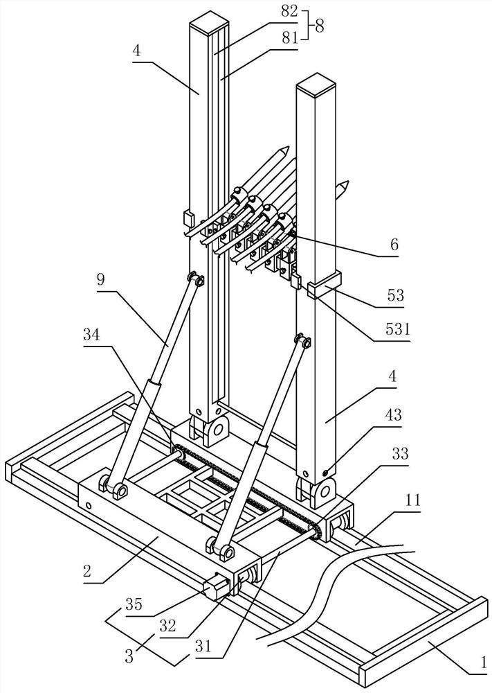
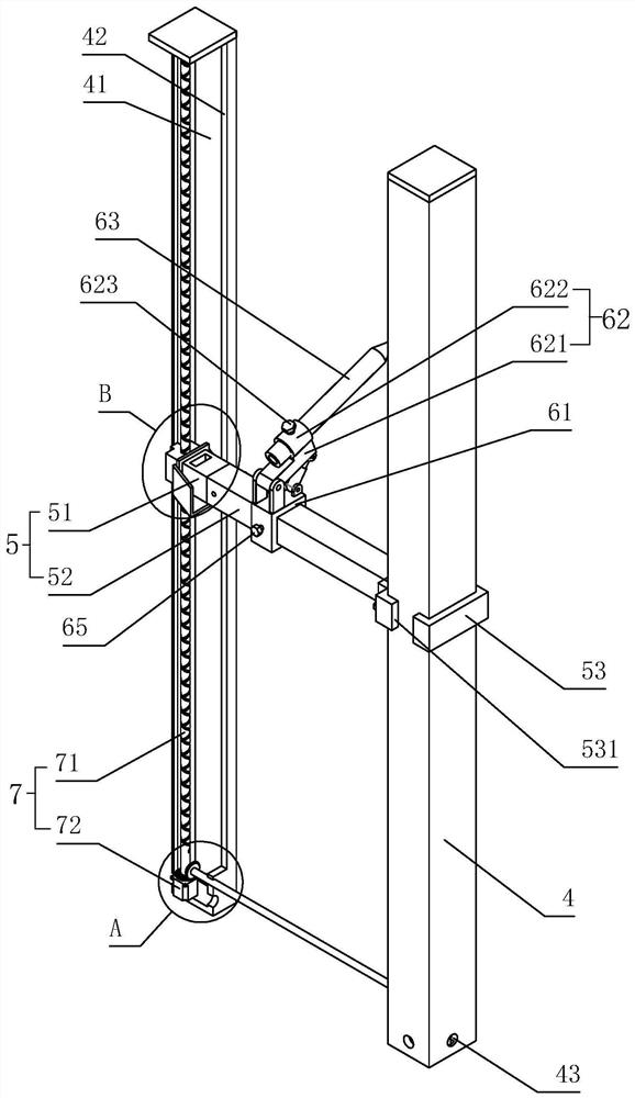
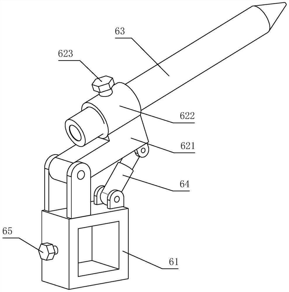
[0049] The embodiment of the present application discloses a wall surface automatic napping device, referring to figure 1 , including a rectangular horizontal guide rail frame 1, a sliding trolley 2 connected to the horizontal rail frame 1 along the length direction of the horizontal rail frame 1, a first drive mechanism 3 for driving the sliding trolley 2 to slide, a pair of hinged The guide rail column 4 on the sliding trolley 2 and parallel to the wall, the support beam 5 connected to the guide rail column 4 along the length direction of the guide rail column 4, the second drive mechanism 7 that drives the support beam 5 to slide, and is arranged on the support On the beam 5, a roughening mechanism 6 is used to roughen the wall surface in the form of high-pressure water jets. The sliding trolley 2 is provided with an adjusting member 9 for adjusting the inclination angle of the ...


PUM


Abstract

The invention relates to an automatic wall surface roughening device. The automatic wall surface roughening device comprises a horizontal guide rail frame, a sliding trolley slidably connected to thehorizontal guide rail frame in the length direction of the horizontal guide rail frame, a first driving mechanism for driving the sliding trolley to slide, a pair of guide rail columns arranged on thesliding trolley and parallel to the wall surface, supporting beams slidably connected to the guide rail columns in the length direction of the guide rail columns, a second driving mechanism for driving the supporting beams to slide and roughening mechanisms arranged on the supporting beams to roughen the wall surface in the form of high-pressure water jet. The automatic wall surface roughening device has the effect of ensuring the quality of roughening of the wall surface.

Description

technical field [0001] The present application relates to the technical field of building wall surface construction, in particular to an automatic wall surface roughening device and a wall surface construction method thereof. Background technique [0002] With the development of building industrialization, casting walls with aluminum alloy formwork has become an essential process for wall pouring. A typical feature of this process is that the surface of the poured wall is very smooth and flat, and the practicability and aesthetics of this process It is self-evident, however, for some walls that still need to be tiled in the future, an overly smooth wall is not conducive to the bonding between the tiles and the wall. If the smooth wall is not roughened, the tiles are easy to fall off. Therefore, Essential for roughening smooth walls. [0003] At present, there are generally two types of napping equipment, one is powered by machinery, and the other is powered by high-pressure...

Claims


Application Information

Patent Timeline
IPC IPC(8): E04F21/16E04G21/00
CPCE04F21/16E04G21/00
Inventor 肖剑波刘幼红吴耐生
Owner 福建大华建设工程股份有限公司
Learn More