Stator structure and brake

A technology of stator structure and brake, applied in the direction of brake actuator, magnetic circuit shape/pattern/structure, and winding insulation shape/pattern/structure, etc., can solve the problems of small coil resistance, small braking force, low efficiency, etc.

Inactive Publication Date: 2020-10-20
GREE ELECTRIC APPLIANCES INC
View PDF9 Cites 0 Cited by
  • Summary
  • Abstract
  • Description
  • Claims
  • Application Information

AI Technical Summary

Problems solved by technology

However, in this coil structure, the skeleton occupies the slot space of the stator core, and the proportion is generally 10% to 20%, which affects the slot full rate (copper wire occupies the slot space ratio)
This results in a relatively small coil resistance, resulting in high power, high heat generation, and low efficiency; and the ampere-turns are low, and the braking force is small

Method used


Image

  • Stator structure and brake
  • Stator structure and brake

Examples


Embodiment Construction

[0022] The following will clearly and completely describe the technical solutions in the embodiments of the present invention with reference to the drawings in the embodiments of the present invention. Apparently, the described embodiments are only some of the embodiments of the present invention, but not all of them. The following description of at least one exemplary embodiment is merely illustrative in nature and in no way taken as limiting the invention, its application or uses. Based on the embodiments of the present invention, all other embodiments obtained by persons of ordinary skill in the art without creative efforts fall within the protection scope of the present invention.

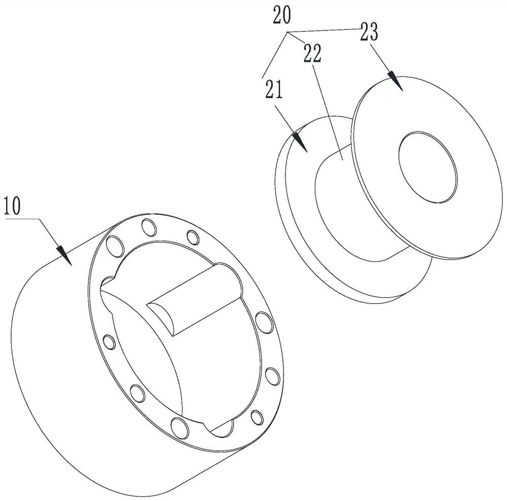
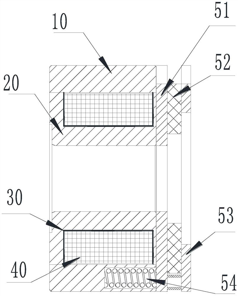
[0023] As shown in the drawings, the embodiment of the present invention provides a stator structure, the stator structure includes a stator core, and the stator core includes: an outer split body 10, the outer split body 10 is an annular structure; an inner split body 20, pierced In the outer...


PUM


Abstract

The invention provides a stator structure and a brake. The stator structure comprises a stator iron core, wherein the stator iron core comprises an outer split body and an inner split body, the outersplit body is of a ring-shaped structure; the inner split body is arranged in the outer split body in a penetrating mode; the inner split body comprises a base, a column body and side wings, and the base and the side wings are separately positioned at the two ends of the column body; in the radial direction of the column body, the dimension of the base and the dimensions of the side wings are greater than the dimension of the column body; an area among the base, the column body, the side wings and the outer split body defines an accommodating cavity for arranging a coil; and the base and the side wings are separately used for limiting the two ends of the coil. With the adoption of the technical scheme, the stator iron core is set to be a split structure, the coil can be directly wound on the column body of the inner split body, and the inner split body is assembled into the outer split body after the coil is wound, so that the original framework can be cancelled; and moreover, the baseand the side wings separately limit the two ends of the coil, and winding of the coil is relatively compact, so that winding turn number can be increased within a limited space, and a slot full rateis increased.

Description

technical field [0001] The invention relates to the technical field of brakes, in particular to a stator structure and a brake. Background technique [0002] Electromagnetic brake is an important basic component, which integrates machinery and electricity, and is mainly used for precise control and braking of rotating mechanisms (such as motor devices, etc.). [0003] The energized state of the brake depends on the energization of the coil placed in the groove of the stator core to generate a magnetic field (electromagnetic force) to attract the armature to overcome the spring force to generate axial displacement, and then release the friction plate assembly clamped by the armature and the limit plate, so that the friction plate And the shaft connected with it can rotate; correspondingly, when the brake is powered off, the armature is axially acted by the spring force, together with the fixed limit plate to clamp the friction plate, making it axially stressed, when the conne...

Claims


Application Information

Patent Timeline
Patent Type & Authority Applications(China)
IPC IPC(8): F16D65/14H02K1/16H02K1/02H02K3/34H02K3/46F16D121/20
CPCF16D65/14F16D2121/20H02K1/02H02K1/16H02K3/34H02K3/46
Inventor 车礼超杨一邱克难巫泽风
Owner GREE ELECTRIC APPLIANCES INC
Why Eureka
Try Eureka