Eureka AIR delivers breakthrough ideas for toughest innovation challenges, trusted by R&D personnel around the world.

Automatic winding machine

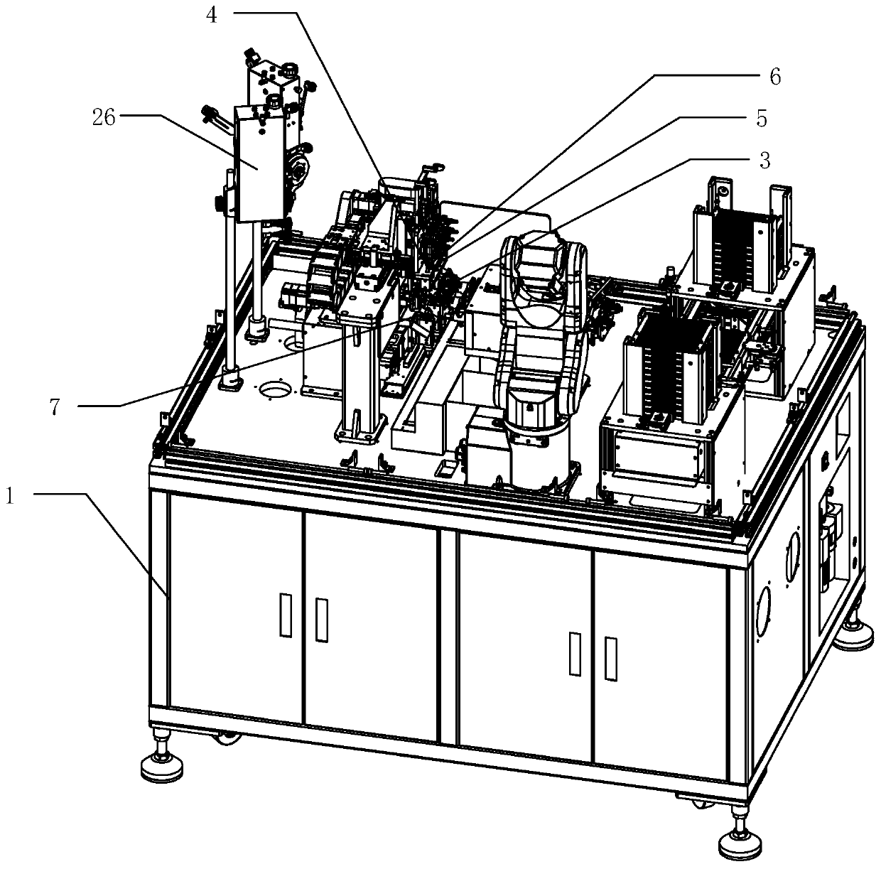
A technology of automatic winding machine and winding head, which is applied in the manufacture of coils, electrical components, inductors/transformers/magnets, etc. It can solve the problems of copper wire interweaving disorder, copper wire not wound firmly, unstable quality, etc., to achieve The winding of copper wire is tight and orderly, and the effect of cutting wire is convenient and quick

Pending Publication Date: 2019-11-26
广东昭信智能装备有限公司
View PDF0 Cites 7 Cited by
  • Summary
  • Abstract
  • Description
  • Claims
  • Application Information

AI Technical Summary

Problems solved by technology

[0002] With the advancement and development of science and technology, the traditional terminal manual winding method is gradually replaced by the mechanical winding method. The existing terminal winding mechanical equipment is relatively simple. The copper wire is drawn out from the nozzle. The wire nozzle not only plays the role of leading the wire, but also plays the role of winding the wire. The wire nozzle is used to wind the copper wire around the terminal and fix it, and the rotating column is started to rotate so that the copper wire is wound on the terminal. The terminal products produced by the winding structure are poor, the quality is unstable, and the copper wires are not firmly wound, the copper wires are intertwined, and the production efficiency is low. After each winding is completed, it is necessary to wait for the unloading and loading. , and then proceed to the next processing and production

Method used

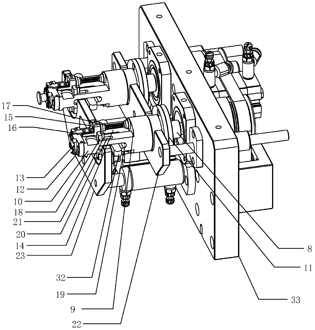
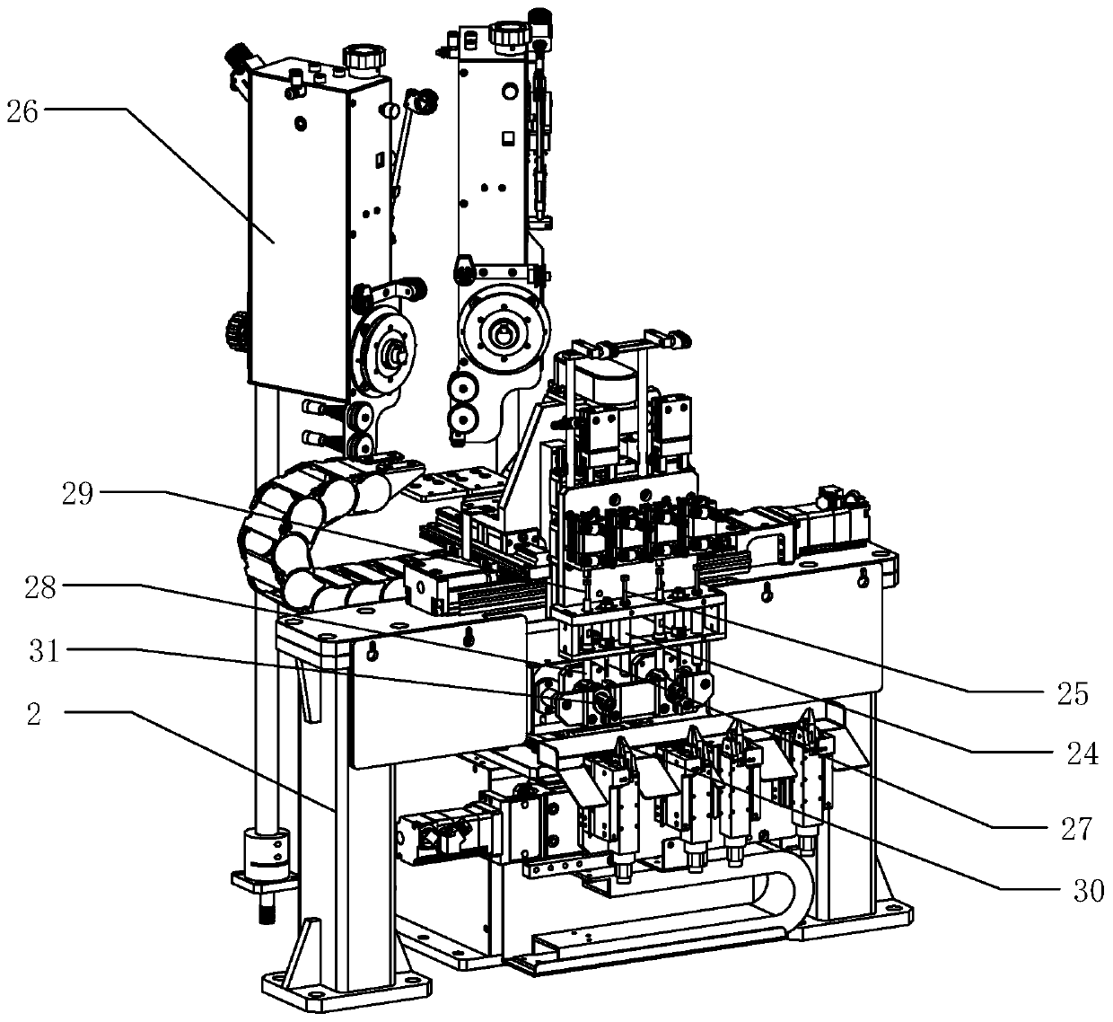

Image

  • Automatic winding machine
  • Automatic winding machine
  • Automatic winding machine

Examples


Embodiment Construction

[0021] The idea, specific structure and technical effects of the present invention will be clearly and completely described below in conjunction with the embodiments and accompanying drawings, so as to fully understand the purpose, features and effects of the present invention. Apparently, the described embodiments are only some of the embodiments of the present invention, rather than all of them. Based on the embodiments of the present invention, other embodiments obtained by those skilled in the art without creative efforts belong to The protection scope of the present invention. In addition, all connection relationships mentioned in this article do not refer to the direct connection of components, but mean that a better connection structure can be formed by adding or reducing connection accessories according to specific implementation conditions. The various technical features in the invention can be combined interactively on the premise of not conflicting with each other. ...


PUM


Abstract

The invention discloses an automatic winding machine. The automatic winding machine comprises a machine frame, which is provided with a rotary motor, a portal frame, a mechanical arm, and a tray support. The tray support is connected with a rotary table in a driving way, and the rotary table is provided with a winding head, which is provided with a work piece accommodating groove. The tray supportis disposed on the right side of the rotary table, and the portal frame is provided with a forward and backward translation device, which is connected with a forward and backward translation plate ina driving way. The forward and backward translation plate is provided with a left and right translation device, which is connected with a left and right translation plate in a driving way. The left and right translation plate is provided with an elevating driving device, which is connected with an elevating plate in a driving way. The elevating plate is provided with an upper wire cutting assembly, a wire leading assembly, and wire clamping assembly. A lower part of a winding head is provided with a lower wire cutting assembly. The winding efficiency is improved, and the winding is stricter and ordered, and the quality is higher.

Description

technical field [0001] The invention relates to terminal production equipment, in particular to an automatic winding machine. Background technique [0002] With the advancement and development of science and technology, the traditional terminal manual winding method is gradually replaced by the mechanical winding method. The existing terminal winding mechanical equipment is relatively simple. The copper wire is drawn out from the nozzle. The wire nozzle not only plays the role of leading the wire, but also plays the role of winding the wire. The wire nozzle is used to wind the copper wire around the terminal and fix it, and the rotating column is started to rotate so that the copper wire is wound on the terminal. The terminal products produced by the winding structure are poor, the quality is unstable, and the copper wires are not firmly wound, the copper wires are intertwined, and the production efficiency is low. After each winding is completed, it is necessary to wait for...

Claims


Application Information

Patent Timeline
Patent Type & Authority Applications(China)
IPC IPC(8): H01F41/06H01F41/09H01F41/076
CPCH01F41/06H01F41/09H01F41/076
Inventor 谢伟平袁达黄孔文李培涛刘海霞
Owner 广东昭信智能装备有限公司
Why Eureka
Eureka Blog
Learn More