Electrically heatable liquid line

a heat-insulating liquid and electric technology, applied in the direction of machines/engines, combustion-air/fuel-air treatment, lighting and heating apparatus, etc., can solve the problems of time-consuming and energy-consuming vulcanizing procedures, and therefore, high cos

Active Publication Date: 2006-02-07
NORMA GERMANY GMBH
View PDF11 Cites 7 Cited by
  • Summary
  • Abstract
  • Description
  • Claims
  • Application Information

AI Technical Summary

Benefits of technology

[0007]The object of the present invention is to provide a liquid line of the above-described type whose manufacture is simpler.
[0009]The solution according to the present invention makes it possible that the adhesive tape can be wound onto the plastic layer in a simple manner, for example, by means of an automatic winding machine or even by hand, or possibly by means of a simple winding device. In accordance with a preferred feature, the adhesive tape includes a textile strip which is coated on one side thereof with adhesive. Such an adhesive tape has a high tensile strength and can therefore be wound very tightly. Moreover, the side of the tape facing outwardly after winding is not adhesive.
[0010]The heating wire can be wound helically or spirally around the plastic layer. Because of the resulting spatial concentration, the heating power of the surface area is relatively high, so that the liquid is quickly heated even if the heating power is relatively low, when the tape is not wound up. The high heating power per surface area can also be achieved by winding the heating wire around the plastic layer in the form of a double helix and to provide the heating wire with an electrically insulating cover. Consequently, the adjacent wire sections can be arranged relatively closely next to each other without producing a short circuit.
[0011]The heating wire preferably forms a loop. The loop makes it possible to wind the forward and return lines of the heating wire in a simple manner simultaneously onto the plastic layer.
[0012]The ends of the heating wire are preferably connected to a plug. As a result, the heating wire can be connected in a simple manner to a voltage source.

Problems solved by technology

The vulcanizing procedure is time-consuming and energy-consuming and, therefore, is expensive.

Method used


Image

  • Electrically heatable liquid line
  • Electrically heatable liquid line

Examples


Embodiment Construction

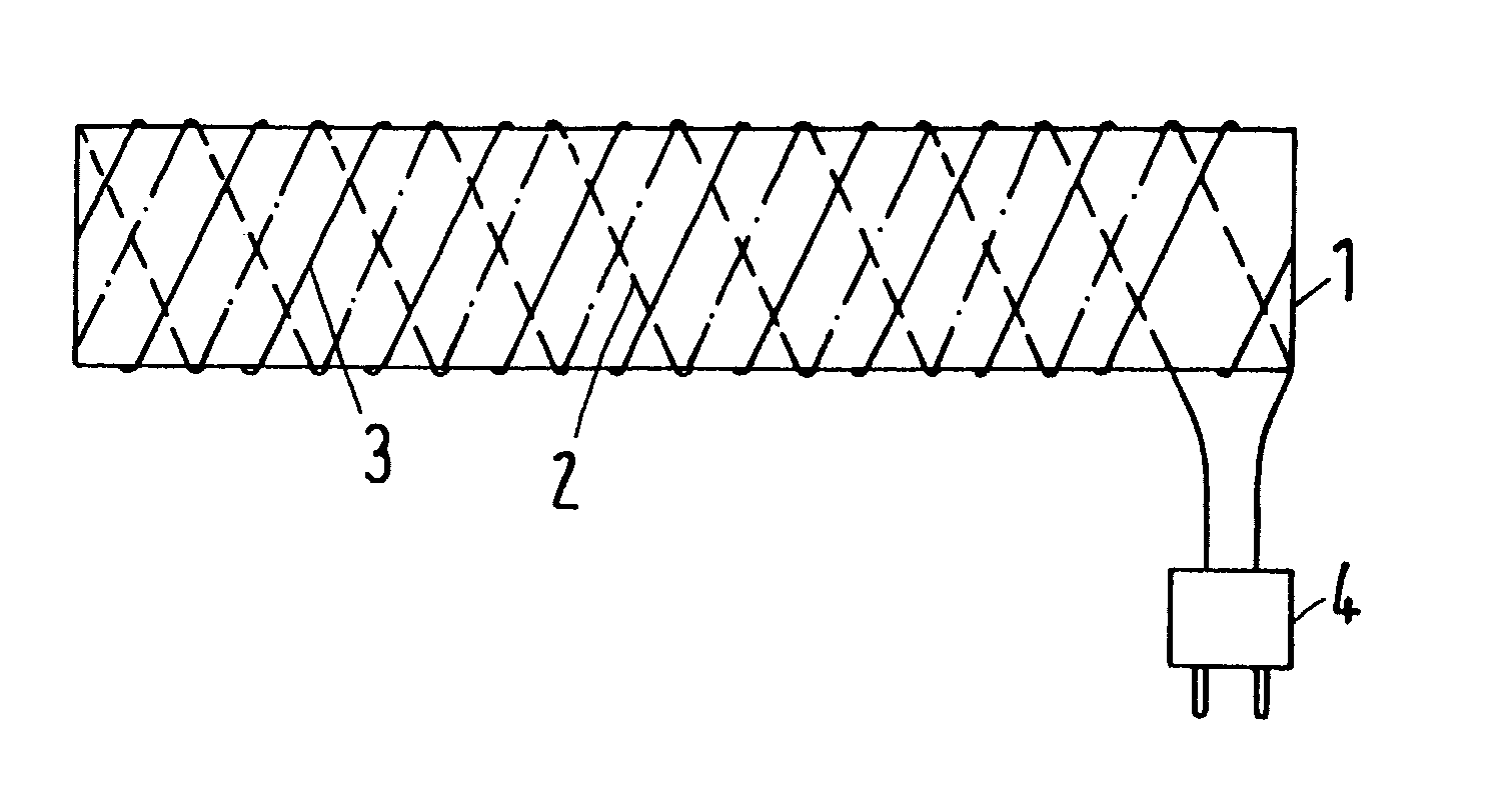
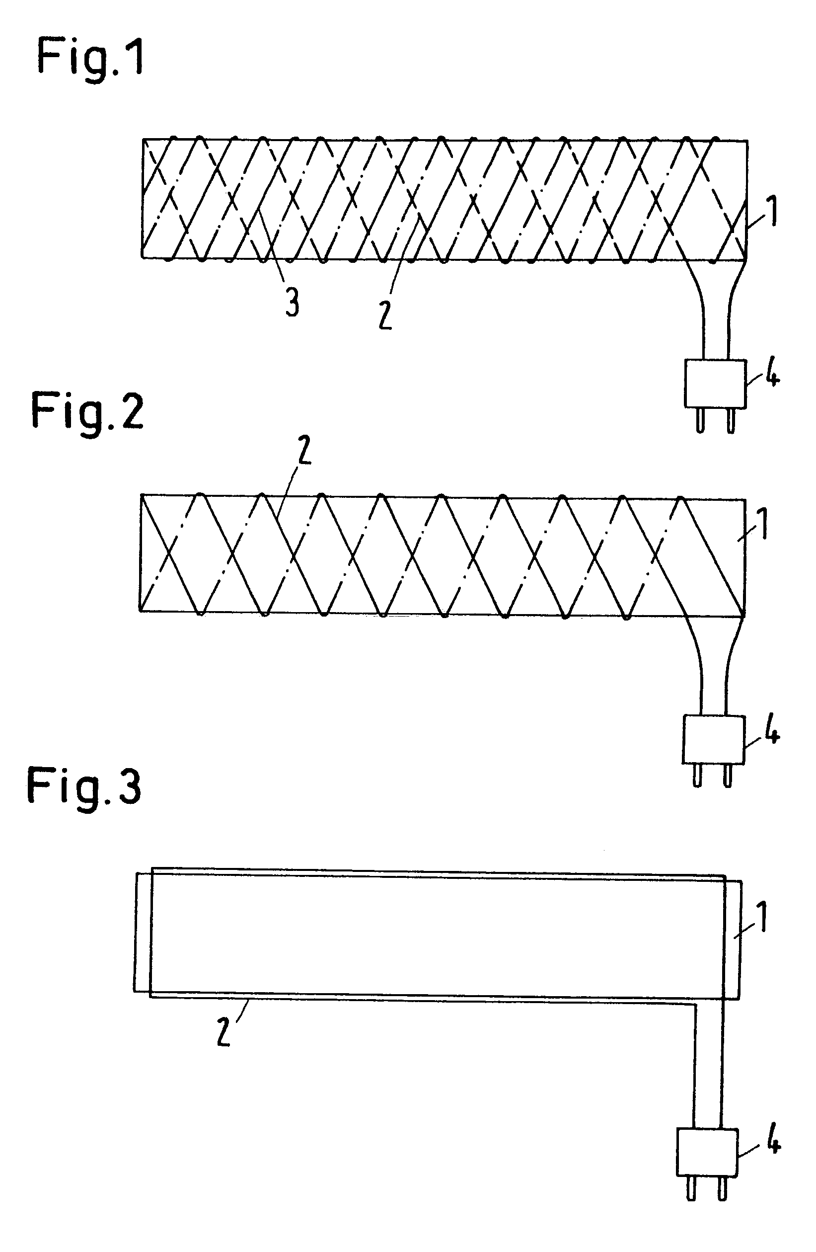
[0018]The liquid lines illustrated in FIGS. 1–3 have an inner tubular or hose-like flexible plastic layer 1 and a heating wire 2 in the form of a resistance wire arranged on the plastic layer 1. In both embodiments, an electrically insulating tape 3 is helically wound onto the plastic layer 1 and the heating wire 2. The tape 3 is not illustrated in FIGS. 2 and 3 in order to make it easier to recognize the pattern of the heating wire 2.

[0019]The insulating tape 3 is an adhesive tape whose adhesive can be glued to the plastic layer 1. The tape 3 includes a textile strip which is on one side thereof coated with adhesive; the textile strip provides the tape with a high tear resistance.

[0020]In the embodiment according to the FIGS. 1 and 2, the heating wire forms a loop which is wound helically in the form of a double helix onto the plastic layer 1.

[0021]In the embodiment of FIG. 3, the heating wire 2 also forms a loop whose forward and return lines extend straight on sides of the plasti...


PUM


Abstract

An electrically heatable liquid line in which a heating wire is arranged on an inner plastic layer and an electrically insulating tape is helically wound around the plastic layer and the heating wire. This object is met in the liquid line of the above-type by providing the insulating tape as an adhesive tape whose adhesive can be glued to the plastic layer.

Description

BACKGROUND OF THE INVENTION[0001]1. Field of the Invention[0002]The present invention relates to an electrically heatable liquid line in which a heating wire is arranged on an inner plastic layer and an electrically insulating tape is helically wound around the plastic layer and the heating wire.[0003]2. Description of the Related Art[0004]The preferred field of application of the liquid line are urea, for example, so-called “AdBlue”, which are injected for the aftertreatment of the waste gas of diesel-operated vehicles into the exhaust gas line in order to reduce toxic NOx components into normal components of the air, i.e., nitrogen, water and carbon dioxide. However, the liquid line is also suitable for diesel fuels, water, such as cooling or washing water, or brake oil in motor vehicles. By heating the liquid line, freezing of the urea, the diesel fuels or the water can be prevented and / or preheating of the diesel fuels can be achieved.[0005]In a known commercially available liqu...

Claims


Application Information

Patent Timeline
Patent Type & Authority Patents(United States)
IPC IPC(8): F24H1/10H05B3/02F01N3/20F01N3/36F02M31/12F02M31/125F16L11/12F16L53/38F24H1/14H05B3/10H05B3/16
CPCF01N3/2066F16L11/127F16L53/008H05B3/16F02M31/125F01N2240/16F01N2610/02F01N2610/03F01N2610/10F01N2610/1486Y02T10/24H05B2203/022Y02T10/126F16L53/38Y02A50/20Y02T10/12
Inventor AUBER, HEIKO
Owner NORMA GERMANY GMBH
Why Eureka
Try Eureka