

Temporary intelligent monitoring device
An intelligent monitoring and temporary technology, applied in traffic control systems, traffic control systems of road vehicles, televisions, etc., can solve problems such as time-consuming and difficult to adjust angles
- Summary
- Abstract
- Description
- Claims
- Application Information
AI Technical Summary
Problems solved by technology
Method used
Image

Examples
Embodiment 1
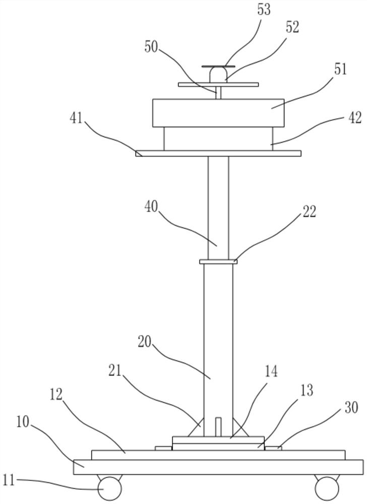
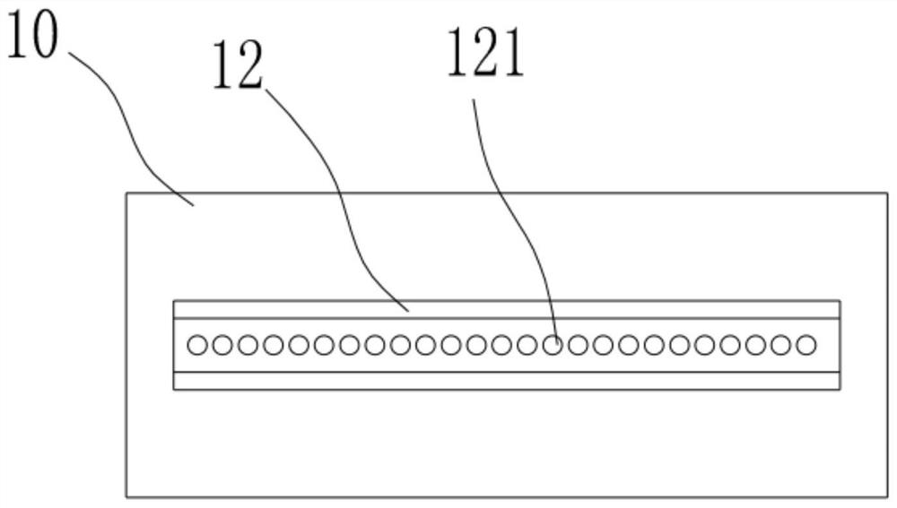
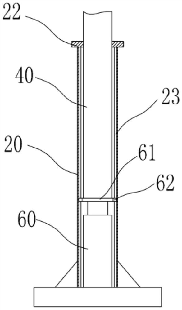
[0030] see Figure 1-7 , the present invention provides a technical solution: a temporary intelligent monitoring device, including a support platform 10, an adjustment mechanism and a telescopic mechanism, the upper end of the support platform 10 is provided with a slide rail 12, and a plurality of through holes 121 are evenly distributed on the bottom wall of the slide rail 12 , a plurality of through holes 121 run through the support platform 10, and a plurality of through holes 121 form a drainage groove, so that rainwater will not accumulate in the slide rail 12, and can be directly discharged through the through holes 121; the slide rail 12 is provided with a slider 13, and the slide Block 13 is connected with fixed plate 14, and sleeve 20 is installed on the fixed plate 14, is provided with chute 23 on the inner wall of sleeve 20, and sleeve rod 40 is installed in the sleeve 20, and sleeve rod 40 upper end is connected with placement plate 41, places The plate 41 is prov...
Embodiment 2
[0038] On the basis of Example 1, please refer to Figure 1-8 , a wireless receiving device is installed on the camera 52, the wireless receiving device is connected with a controller, the wireless receiving device and the controller are not shown in the figure, the controller is connected with the first driving motor 80, the second driving motor 70 and the first hydraulic The cylinder 60 is connected, and a horn 90 is installed on the lower side of the connecting plate, and the horn 90 is connected with a wireless receiving device, and the remote signal can be received by the wireless receiving device and sent to the controller and the horn 90, and the controller controls the first drive motor 80 and the second drive motor 70 and the first hydraulic cylinder 60 can remotely control the monitoring device, adjust the monitoring height, monitoring direction and monitoring angle of the camera 52 in real time, and realize full coverage of the monitoring site. The horn 90 receives t...
PUM
 Abstract
Description
Claims
Application Information