Optical encoder
A technology of optical encoders and light sources, applied in the field of optical encoders, can solve the problems of incomplete INC patterns, lossy and accurate detection, etc.
- Summary
- Abstract
- Description
- Claims
- Application Information
AI Technical Summary
Problems solved by technology
Method used
Image

Examples
no. 1 example
[0034] Reference below Figure 1 to Figure 5 A first embodiment of the present invention is described.
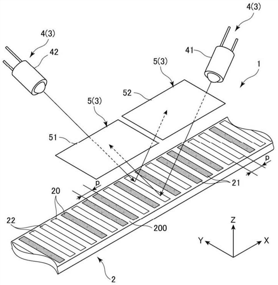
[0035] In each drawing, the long direction of the scale 2 of the optical encoder 1 is shown as the X direction, the short direction is shown as the Y direction, and the height direction is shown as the Z direction. The description below may be provided simply using the terms X-direction, Y-direction and Z-direction. figure 1 is a perspective view of the optical encoder 1 according to the first embodiment of the present invention.
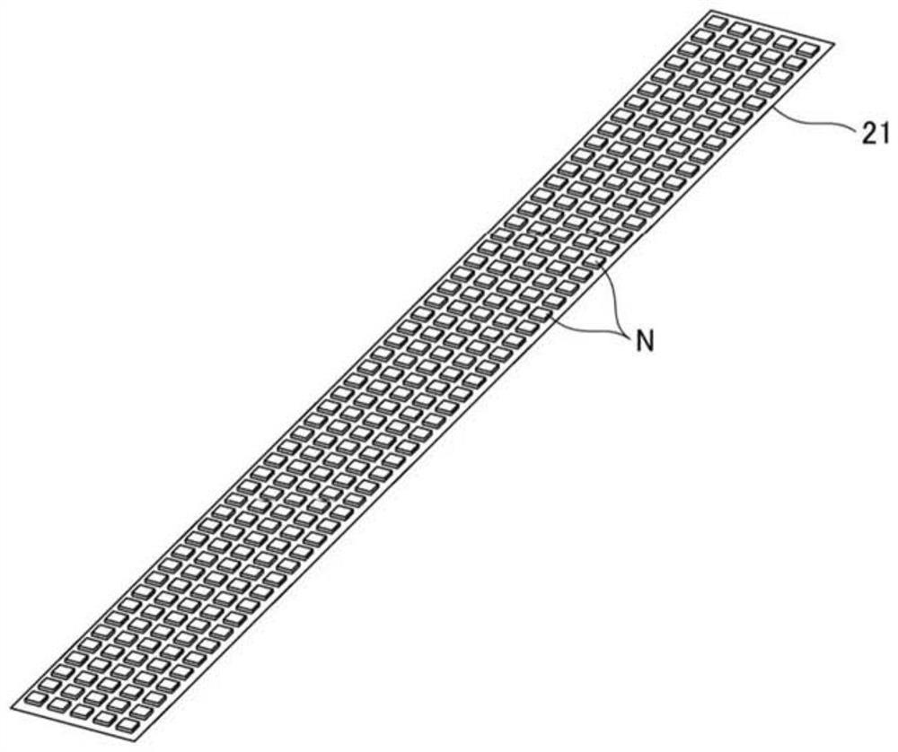
[0036] Such as figure 1 As shown, the optical encoder 1 comprises a long scale 2 and a head 3 which faces the scale 2 and is displaced relative to the scale 2 along the X direction (measurement direction). The optical encoder 1 is a linear encoder used in a linear scale which is a measuring device not shown in the figure. Optical encoder 1 is provided inside the linear scale. The linear scale detects the position of the head 3 relative to th...
no. 2 example
[0059] Reference below Image 6 A second embodiment of the present invention is described. In the following description, those parts that have been described previously are assigned the same reference numerals, and descriptions thereof are omitted. Image 6 is a perspective view showing an optical encoder 1A according to a second embodiment of the present invention. The optical encoder 1A of the second embodiment has a basically similar configuration to the optical encoder 1 of the first embodiment, except that the optical encoder 1A includes a head portion 3A.
[0060] The head 3 of the optical encoder 1 of the first embodiment includes a light source 4 and an image capturer 5, and as figure 1 As shown, the light source 4 includes a first light source 41 and a second light source 42 . The head 3A of the optical encoder 1A of the second embodiment is different from the first embodiment in that the head 3A further includes a single light source 4A, and the light arriving via...
no. 3 example
[0065] Reference below Figure 7 A third embodiment of the present invention is described. In the following description, those parts that have been described previously are assigned the same reference numerals, and descriptions thereof are omitted. Figure 7 is a perspective view showing an optical encoder 1B according to a third embodiment of the present invention. The optical encoder 1B of the third embodiment has a basically similar configuration to the optical encoder 1A of the second embodiment except that the optical encoder 1B includes a head 3B.
[0066] The head 3A of the optical encoder 1A of the second embodiment includes a single light source 4A and a dispersion component 10, such as Image 6 shown. The head 3B of the optical encoder 1B of the third embodiment differs from the second embodiment in that the head 3B does not include the dispersion component 10, and in that the first image capturing section 51B of the image capture 5B and the second image capturin...
PUM
 Abstract
Description
Claims
Application Information
 - R&D
- Intellectual Property
- Life Sciences
- Materials
- Tech Scout
- Unparalleled Data Quality
- Higher Quality Content
- 60% Fewer Hallucinations
Browse by: Latest US Patents, China's latest patents, Technical Efficacy Thesaurus, Application Domain, Technology Topic, Popular Technical Reports.
© 2025 PatSnap. All rights reserved.Legal|Privacy policy|Modern Slavery Act Transparency Statement|Sitemap|About US| Contact US: help@patsnap.com