Dynamic illumination system for airborne vehicles

A lighting system and vehicle technology, applied in the field of dynamic lighting systems, can solve problems such as less consideration of the position and shape of moving surfaces

Inactive Publication Date: 2020-10-20
AIRBUS OPERATIONS GMBH +1
View PDF3 Cites 0 Cited by
  • Summary
  • Abstract
  • Description
  • Claims
  • Application Information

AI Technical Summary

Problems solved by technology

However, such systems rarely take into account the position and shape of the moving surface to be illuminated

Method used


Image

  • Dynamic illumination system for airborne vehicles
  • Dynamic illumination system for airborne vehicles
  • Dynamic illumination system for airborne vehicles

Examples


Embodiment Construction

[0025] While specific embodiments have been shown and described herein, it should be understood by those of ordinary skill in the art that various alternative and / or equivalent implementations may be used without departing from the scope of the present invention manner in lieu of the specific embodiment shown and described. In general, this application is intended to cover any adaptations or variations of the specific embodiments discussed herein.

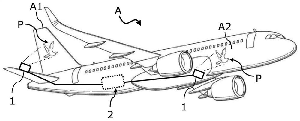
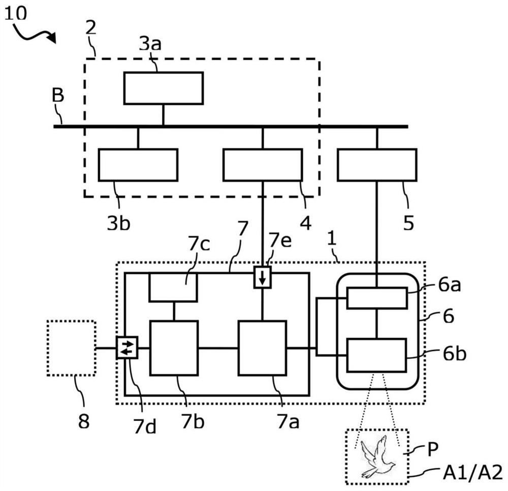
[0026] figure 1 A schematic representation of an aircraft A with a dynamic lighting system 1 with lighting projectors and an avionics network 2 as part of the lighting system of the aircraft A is shown. figure 2 A functional block diagram illustrating the parts and elements of a lighting system architecture 10 - for example for use in vehicles such as in figure 1 An air vehicle exemplarily depicted with reference numeral A in . Within the meaning of the present disclosure, air vehicles include all types of vehicles that can be ...


PUM


Abstract

An illumination system (1) for illuminating outer aircraft components of an airborne vehicle (A), such as an aircraft, includes a light projection system (6) configured to project visual imagery (P) to an outer surface of the airborne vehicle (A), and a projection controller (7) having a light control processor (7a) configured to control the operation of the light projection system (6) on the basis of at least one of operational flight status of the airborne vehicle (A), geographical location of the airborne vehicle (A) and configuration data of movable surfaces of the airborne vehicle (A) oron ambient light measurement.

Description

technical field [0001] The invention relates to a dynamic lighting system for an air vehicle, an air vehicle equipped with such a dynamic lighting system, and a method for dynamically lighting an exterior part of an aircraft. [0002] Although applicable to any type of air vehicle, the invention and the corresponding potential problems will be explained in more detail in connection with an aircraft. Within the meaning of the present disclosure, air vehicles include all types of vehicles that can be propelled through the air by force and / or supported by aerodynamic forces. Background technique [0003] Aerial vehicles often employ static pictures, logos, or decals painted or attached to the exterior of the vehicle shell. Sometimes static white light is used to highlight certain parts of the otherwise static visual appearance of the air vehicle. In any event, static visual identification contributes only to a limited extent to the attention an air vehicle can attract. In pa...

Claims


Application Information

Patent Timeline
Patent Type & Authority Applications(China)
IPC IPC(8): G09F21/10G09F21/06G09F19/18G03B29/00G03B21/56G03B21/14G03B17/54G03B15/00B64D47/02
CPCB64D47/02G03B15/006G03B17/54G03B21/14G03B21/56G03B29/00G09F19/18G09F21/06G09F21/10B64D47/06B64D2203/00G03B21/60G09G5/38G09G2340/0464G09G2360/144G09G2380/12
Inventor 马泰斯·普洛克尔吕克·扬·霍恩斯特拉弗兰克·尼尔森加布丽埃勒·德布鲁韦
Owner AIRBUS OPERATIONS GMBH
Why Eureka
Try Eureka