
Magnetizing and using method of polygonal magnetic steel

A polygonal, magnetizing direction technology, applied in the direction of magnetic objects, electrical components, circuits, etc., can solve the problems of large loss, high cost of magnetic steel production, limited magnetic field enhancement effect, etc.

Active Publication Date: 2020-10-20
苏州英磁新能源科技有限公司
View PDF12 Cites 0 Cited by
  • Summary
  • Abstract
  • Description
  • Claims
  • Application Information

AI Technical Summary

Problems solved by technology

However, due to the limitation of the structure of the magnet and the original magnetization direction, the magnetization angle of the magnet cannot be freely selected, which makes the magnetic field enhancement effect limited.
And because the production cost of the magnetic steel is relatively high, the magnetizing method in the prior art has a large loss and high cost

Method used


Image

  • Magnetizing and using method of polygonal magnetic steel
  • Magnetizing and using method of polygonal magnetic steel
  • Magnetizing and using method of polygonal magnetic steel

Examples


Embodiment 1

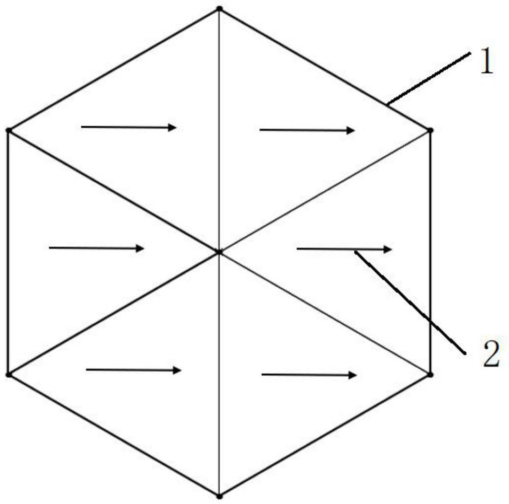
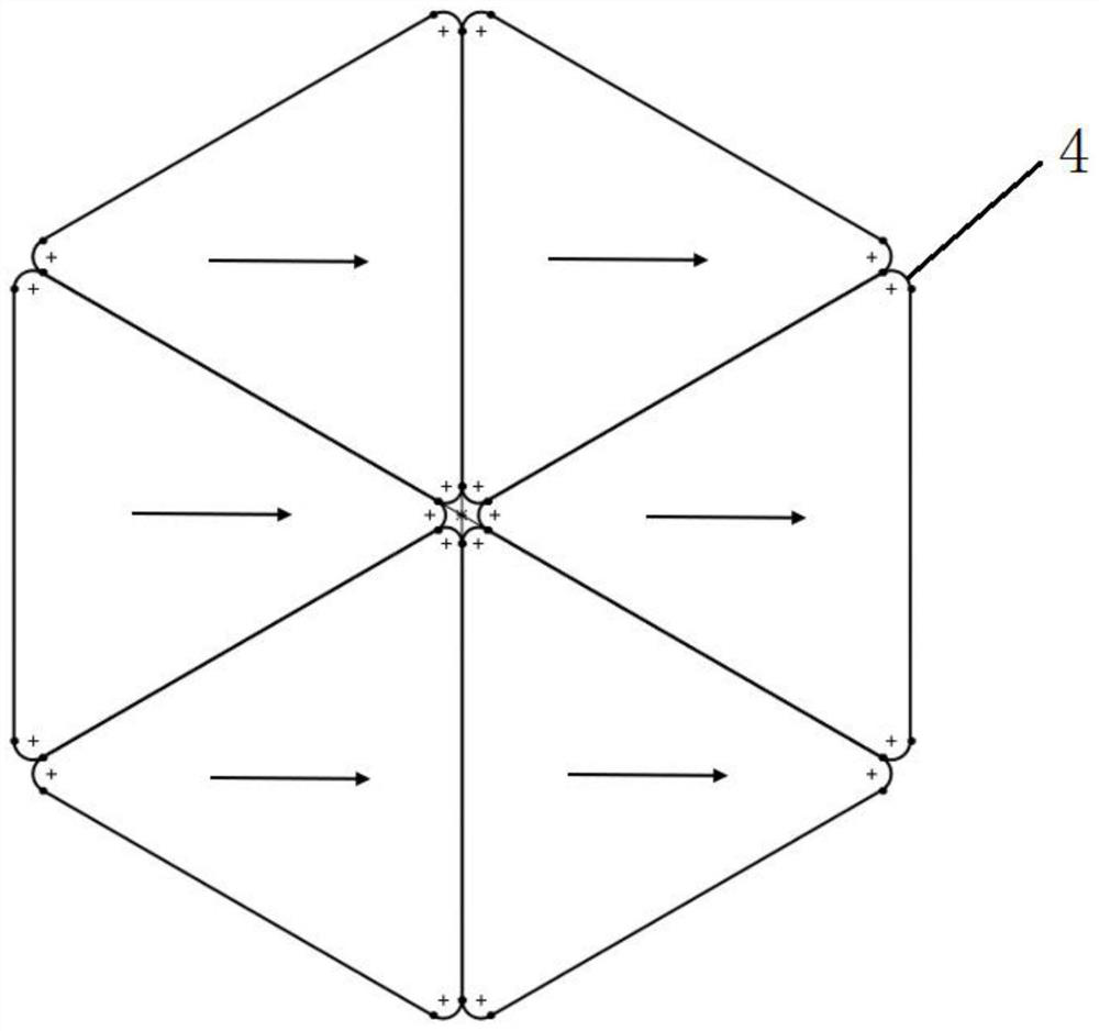
[0032] First, the raw materials are placed in a polygonal mold and sintered into a polygonal material. The polygonal material here is a regular polygon with N sides, and N is a natural number greater than or equal to 3; then, the polygonal material is fixed, and then the polygonal material is processed along the horizontal direction. Polygonal permanent magnets are obtained by unidirectional magnetization; then, the magnetized polygonal permanent magnets are mechanically cut to form multiple polygonal magnets with different magnetization directions and a certain angle between the magnetization direction and the horizontal. The steel is rotated at a certain angle and pieced together into a topological structure.

[0033] The selection of the polygonal material here is based on the topological structure of the polygonal magnetic steel obtained after subsequent cutting. For example, regular hexagons are easy to cut into equilateral triangles and isosceles trapezoidal structures. ...

Embodiment 2

[0036] The polygonal permanent magnet is obtained after the polygonal material is magnetized in the horizontal direction, and the polygonal permanent magnet is cut into the same polygon or two or more polygons of different shapes. The polygonal structure is triangular, quadrilateral, pentagonal or hexagonal.

[0037] Further, the triangle is a regular triangle or an equilateral triangle, the quadrilateral is a parallelogram, the pentagon is a regular pentagon, and the hexagon is a regular hexagon.

[0038] Further, the polygonal magnetic steel here preferably adopts regular triangles, regular pentagons and regular hexagons, and a special shape of hexagons can also be used. This special hexagon is evolved from a regular hexagon, and a A regular hexagon can be regarded as a hexagonal figure composed of three sets of parallel sides. Extend any set of parallel sides at the same distance. 1.5-3.5 times to form a new hexagonal figure.

[0039] In this embodiment, a regular hexagona...


PUM


Abstract

The invention discloses a magnetizing method for polygonal magnetic steel. The method comprises the steps: fixing a polygonal permanent magnet, and then carrying out single-direction magnetizing of the polygonal permanent magnet in a horizontal direction; and cutting the magnetized polygonal permanent magnet to obtain a plurality of polygonal magnetic steel, enabling the formed polygonal magneticsteel to have a plurality of magnetizing directions, forming a certain included angle between the magnetizing directions of the polygonal magnetic steel and the horizontal plane, arranging and rotating the polygonal magnetic steel to be spliced into a permanent magnet track of a topological structure, and enhancing the unilateral gain effect of a magnetic field. Meanwhile, a plurality of polygonalpermanent magnets meeting the magnetizing direction of the design requirement can be obtained at a time; the method is small in loss, low in waste rate, easy and convenient to manufacture and high inproduction efficiency, polygonal magnetic steel in different magnetizing directions is formed after cutting, the splicing requirements of topological structures in different shapes can be met, the applicability is high, cutting in various modes can be conducted at the same time, and application is more flexible.

Description

technical field [0001] The present invention mainly relates to the technical field of polygonal magnets, in particular to a method for magnetizing and using polygonal magnets, and in particular to a method that can magnetize polygonal magnets, obtain multi-angle magnets after cutting, and rotate angles during use. A method of building into an array topology. Background technique [0002] In the prior art, the permanent magnet rail in the traditional superconducting suspension model is only arranged in an N-S manner by several square permanent magnets to form a stable magnetic field. At the same time, in order to enhance the magnetic field above the permanent magnet rail, the permanent magnet is usually selected Rare-earth permanent magnets, even in this way, have very low surface magnetic field strength provided by their orbits, and have a very limited effect on enhancing the levitation force of superconductors. [0003] Such as prior art CN105006192B, CN105810066A, CN10057...

Claims


Application Information

Patent Timeline
Patent Type & Authority Applications(China)
IPC IPC(8): H01F13/00
CPCH01F13/003
Inventor 裴瑞琳高凌宇张航
Owner 苏州英磁新能源科技有限公司
Learn More