Distribution box with buffer base

A distribution box and buffer board technology, applied in electrical components, substation/switch layout details, seismic equipment, etc., can solve the requirements of poor vibration absorption, high performance parameters such as spring elastic limit, and not particularly strong earthquake resistance. functions, etc.

Inactive Publication Date: 2020-10-20
蚌埠普源电气科技有限公司
View PDF1 Cites 2 Cited by
  • Summary
  • Abstract
  • Description
  • Claims
  • Application Information

AI Technical Summary

Problems solved by technology

[0004] However, the above-mentioned distribution box with anti-seismic function still has the following obvious defects during use: the function of shock absorption and buffering is realized through the setting of the shock absorption unit and the tilting rod, and the shock absorption spring in the shock absorption unit and the second The first spring and the second spring connected to the inclined rod are used to absorb the vibration energy, so as to absorb the vibration and achieve the effect of buffering. However, through the structure of the above-mentioned base, although various springs are used together, Only through the setting of the spring, the effect of absorbing vibration is not good, and there are also high requirements for performance parameters such as the elastic limit of the spring, and the base of the above-mentioned distribution box has no other structure that can absorb vibration and achieve buffering. The base as a whole cannot play a particularly strong anti-seismic function

Method used


Image

  • Distribution box with buffer base
  • Distribution box with buffer base
  • Distribution box with buffer base

Examples


Embodiment Construction

[0035] The following will clearly and completely describe the technical solutions in the embodiments of the present invention with reference to the accompanying drawings in the embodiments of the present invention. Obviously, the described embodiments are only some, not all, embodiments of the present invention. Based on the embodiments of the present invention, all other embodiments obtained by persons of ordinary skill in the art without making creative efforts belong to the protection scope of the present invention.

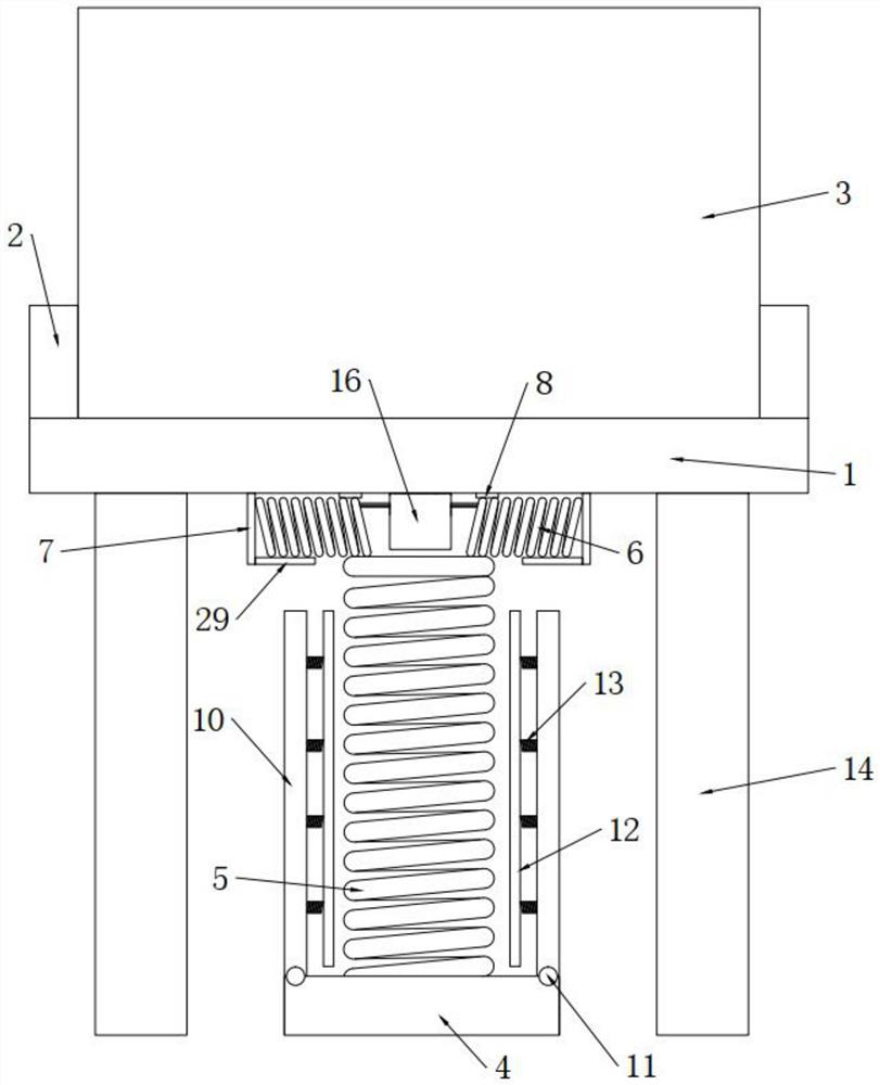
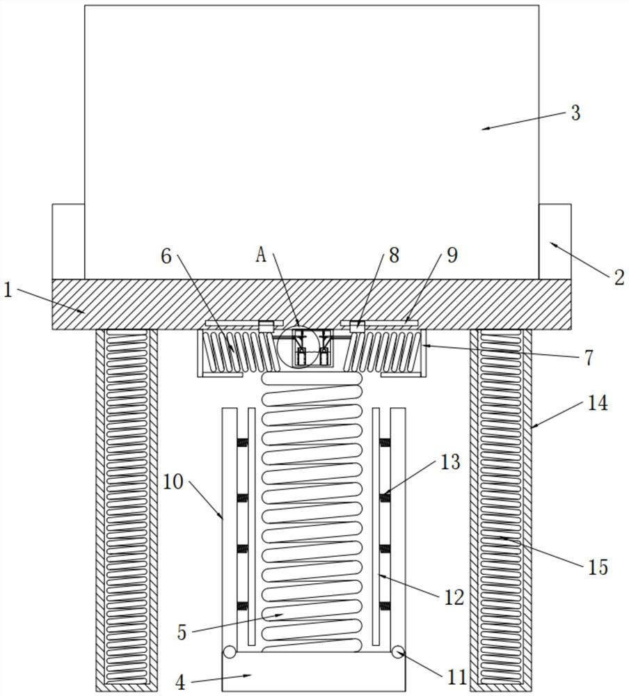
[0036] see Figure 1-15 , the present invention provides a technical solution:

[0037] A distribution box with a buffer base, including a base plate 1, a side plate 2 and a distribution box 3, the side plates 2 are symmetrically fixed on both sides of the base plate 1, and the side plates 2 are used to prevent the distribution box 3 from sliding in the left and right directions , to limit the position of the distribution box 3, the distribution box 3 is set be...


PUM


Abstract

The invention discloses a distribution box with a buffer base. The distribution box with the buffer base comprises a substrate, a side plate and a distribution box, the base is arranged below the substrate, and one side, close to the substrate, of the base is connected with a vertically arranged main spring; a suction buffer box is fixedly arranged between the two side suction springs; an inner cavity is formed in the buffer box, buffer liquid is arranged in the inner cavity, the elastic rope movably penetrates through the side wall of the buffer box and is fixedly connected to the side suction spring on the adjacent side, and one end of a transverse rack movably penetrates through the side wall of the suction buffer box and is fixedly connected to the side suction spring on the adjacent side. According to the invention, the main spring and the side suction springs which are connected with each other are arranged; firstly, shock absorption and buffering are conducted through the main spring, secondly, the main spring can transmit shock force to the side suction springs for absorption and shock resistance, finally, during shock absorption and buffering of the side suction springs, the purpose that the side suction springs absorb shock through liquid for buffering can be further achieved, and the distribution box with the buffer base is very worthy of popularization.

Description

technical field [0001] The invention relates to the technical field of construction equipment buffering, in particular to a distribution box with a buffering base. Background technique [0002] The distribution box is a general circuit distribution box for all users to use electricity. The distribution box requires switchgear, measuring instruments, protective appliances and auxiliary equipment to be assembled in a closed or semi-closed metal cabinet or on a screen to form a low-voltage distribution box. box. During normal operation, the circuit can be connected or disconnected by means of a manual or automatic switch. During the use of the distribution box, or external shocks and earthquakes, the body of the distribution box will vibrate, and the ordinary distribution box is rigidly connected. Moreover, the components in the distribution box are also rigidly connected, and long-term use will bury hidden dangers in accidents. [0003] In the prior art, the notification num...

Claims


Application Information

Patent Timeline
Patent Type & Authority Applications(China)
IPC IPC(8): H02B1/46H02B1/54F16F15/067F16F15/023F16F15/02
CPCF16F15/022F16F15/023F16F15/067H02B1/46H02B1/54
Inventor 沈文齐陈超
Owner 蚌埠普源电气科技有限公司
Why Eureka
Try Eureka