
A fixture for robot motors

A technology of fixing devices and robots, which is applied in the direction of electromechanical devices, electrical components, electric components, etc., can solve the problems of outstanding heat dissipation of motors and poor heat dissipation performance of installation devices, etc., to improve heat dissipation, avoid offset, and improve stability Effect

Active Publication Date: 2021-12-14
重庆新登奇机电技术有限公司 +1
View PDF9 Cites 0 Cited by
  • Summary
  • Abstract
  • Description
  • Claims
  • Application Information

AI Technical Summary

Problems solved by technology

[0003] The main problems in the use of the existing motor are: (1) the protection of the motor, if the robot needs to work in a harsh environment, the motor needs a higher protection level; (2) the heat dissipation problem of the motor on the robot, if the motor In the interior of the robot, and the installation device is required, if the heat dissipation performance of the installation device is not good, the heat dissipation problem of the motor is particularly prominent

Method used


Image

  • A fixture for robot motors
  • A fixture for robot motors
  • A fixture for robot motors

Examples


Embodiment 1

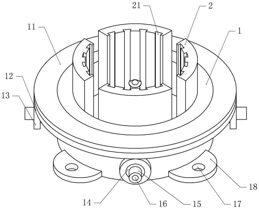
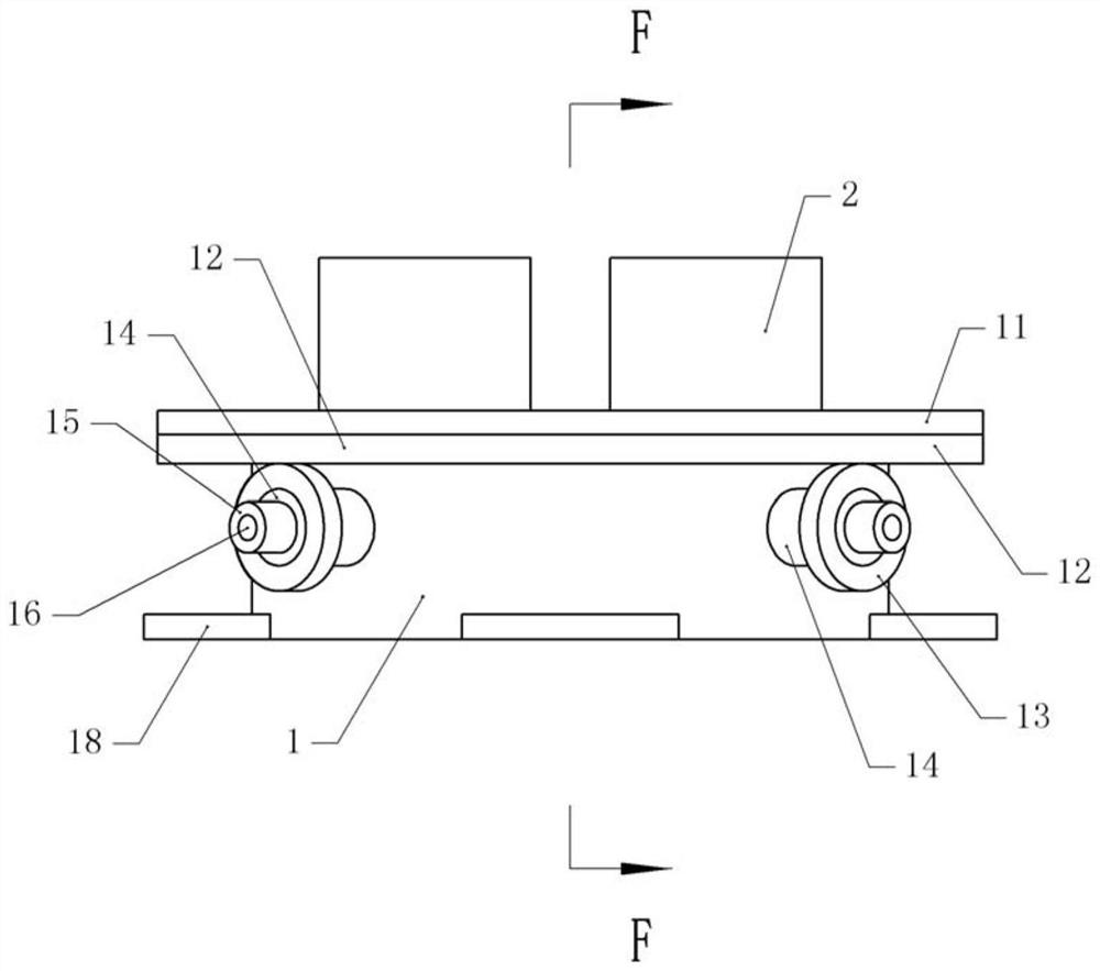
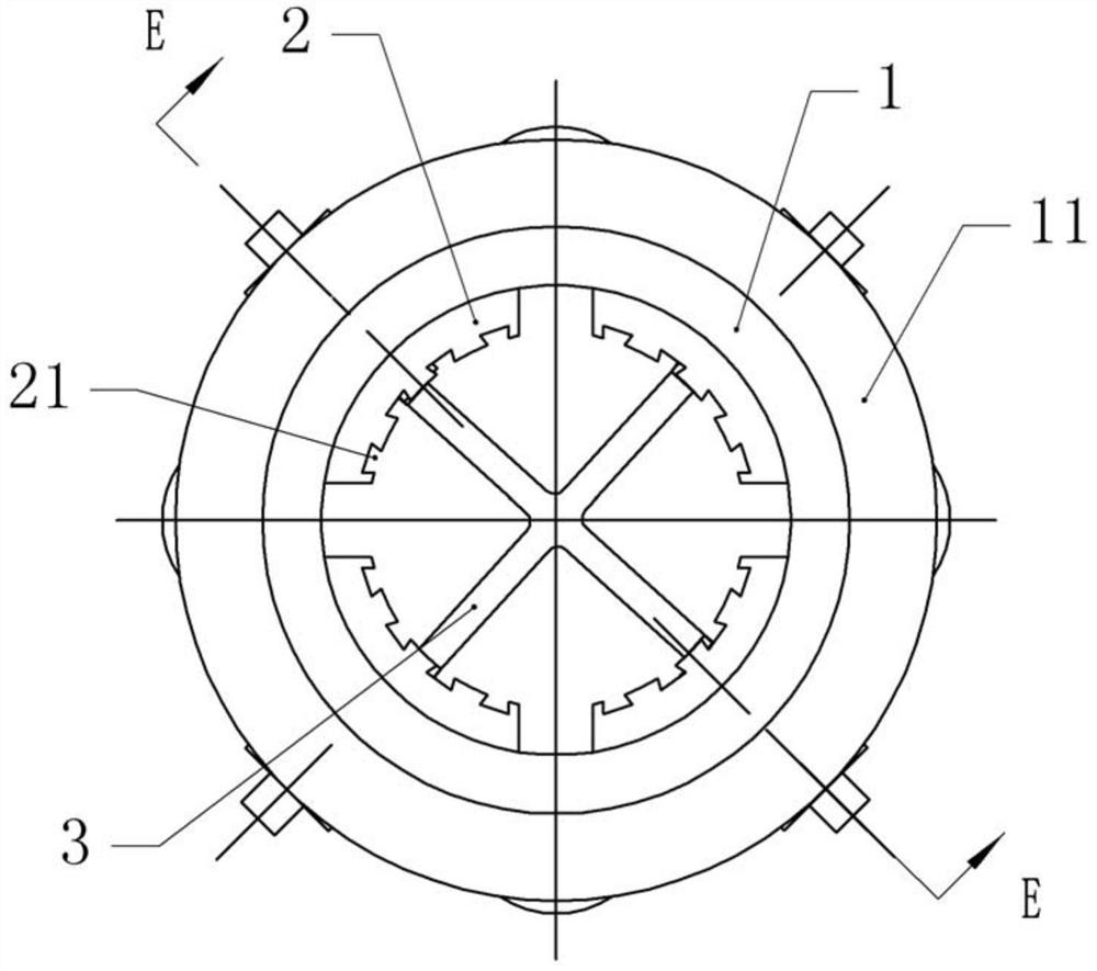
[0040] Basic as attached figure 1 , attached figure 2 And attached image 3 As shown, a fixing device for a robot motor includes a fixing seat 1, and a clamping groove with a circular longitudinal section is opened on the fixing seat 1, and a number of arc-shaped longitudinal sections are evenly distributed in the clamping groove along its circumference. As for the clamping plates 2 , there is a space between two adjacent clamping plates 2 for the heat dissipation of the motor. The bottom of the clamping groove has a chute 3, combined with the attached Figure 5 As shown, the bottom of the clamping plate 2 is welded with a slider 22 horizontally slidingly connected with the chute 3 . A plurality of cooling grooves 21 are formed on the inner side of the clamping plate 2, and the cooling grooves 21 extend to the bottom of the clamping groove.

[0041] combined with Figure 4 And attached Figure 5 As shown, the fixed base 1 is provided with several hollow outer shafts 14 ...

Embodiment 2

[0049] The difference between embodiment two and embodiment one is that, as attached Figure 6 , attached Figure 7 And attached Figure 8 As shown, the bottom of the fixed seat 1 is welded with a support seat 4 with a circular longitudinal section, an adjustment shaft (not shown in the figure) is rotatably connected to the support seat 4, and locking plates 41 are threaded on both sides of the adjustment shaft. .

[0050] When installing the fixing device for the robot motor on the desired position of the robot, first weld the adjusting shaft on the robot, then turn the support base 4, and then the support base 4 carries the fixing base 1 to adjust the orientation of the fixing base 1, Then fix the motor again. The fixed seat 1 is adjusted through the support seat 4 and the adjustment shaft to meet the requirements of different orientations (inclination angles).

[0051] The locking plate 41 is detachably connected with a positioning shaft 42, specifically: the locking pl...


PUM


Abstract

The invention relates to the technical field of fixed installation, and discloses a fixing device for robot motors, which includes a fixing seat and a clamping groove opened on the fixing seat, and a number of clamping plates are evenly distributed along the circumference of the clamping groove, and the clamping The plates are all horizontally slidably connected to the fixing seat, and there is a space for heat dissipation between two adjacent clamping plates; a number of hollow outer shafts are arranged on the fixing seat along its circumference, and the number of the outer shafts is the same as that of the clamping plates. The outer shafts are all rotatably connected with the fixed seats, and the inner shafts of the outer shafts are threaded and connected with the inner shafts fixedly connected with the clamping plate; the outer shafts are coaxially fixed with gears, and the fixed seats are slidably connected with racks meshing with the gears. The invention has a simple structure and can quickly clamp the motor to protect the motor and perform certain heat dissipation.

Description

technical field [0001] The invention relates to the technical field of fixed installation, in particular to a fixing device for a robot motor. Background technique [0002] At present, compact exterior design is the development trend of industrial robots, especially when faced with limited space and complex working environment, this demand is even stronger. The motor is the basic component of the robot, and the robot joint structure related to the motor is an important factor affecting the robot's overall size. The size of the motor itself and its combination with other parts around it, such as the installation device of the motor, will directly affect the use of the motor. [0003] The main problems in the use of the existing motor are: (1) the protection of the motor, if the robot needs to work in a harsh environment, the motor needs a higher protection level; (2) the heat dissipation problem of the motor on the robot, if the motor Inside the robot, a mounting device is ...

Claims


Application Information

Patent Timeline
Patent Type & Authority Patents(China)
IPC IPC(8): H02K5/24H02K5/26H02K5/20H02K7/116
CPCH02K5/24H02K5/26H02K5/20H02K7/116
Inventor 董明海伍国果
Owner 重庆新登奇机电技术有限公司
Learn More