Arrangement for the liquid cooling of electric machine

A technology of liquid cooling and cooling jacket, applied in cooling/ventilation devices, electromechanical devices, electric power devices, etc., can solve problems such as increasing installation space requirements

Pending Publication Date: 2020-10-20
ZF FIEDRICHSHAFEN AG
View PDF1 Cites 0 Cited by
  • Summary
  • Abstract
  • Description
  • Claims
  • Application Information

AI Technical Summary

Problems solved by technology

However, this arrangement increases the installation space requirement, since correspondi

Method used


Image

  • Arrangement for the liquid cooling of electric machine
  • Arrangement for the liquid cooling of electric machine
  • Arrangement for the liquid cooling of electric machine

Examples


Embodiment Construction

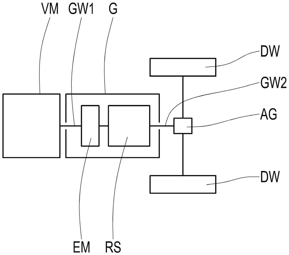
[0022] figure 1 A drive train for a motor vehicle is shown schematically. The drive train has an internal combustion engine VM, the output of which is connected to the input shaft GW1 of the transmission G. The transmission G forms the drive train unit of the drive train. An output shaft GW2 of the transmission G is connected to the differential AG. The differential gear AG is designed to distribute the power applied to the output shaft GW2 to the drive wheels DW which drive the motor vehicle. Transmission G has a gear set RS which is not in figure 1 The shift elements shown in are arranged together between the input shaft GW1 and the output shaft GW2 to provide different transmission ratios. The transmission G has an electric motor EM connected to the input shaft GW1. The electric motor EM is provided for driving the input shaft GW1.

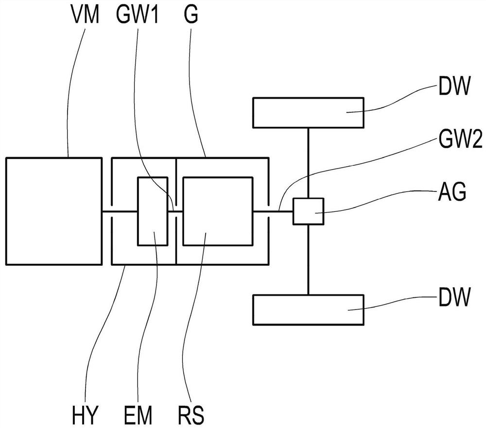
[0023] figure 2 The drive train is shown schematically, with no electric machine included in the transmission G. Instead, a hybrid ...


PUM


Abstract

The invention relates to a device for the liquid cooling of an electric machine (EM) having a stator (S) and a rotor (R), wherein the electric machine (EM) is surrounded by a cooling jacket (M) on theouter circumference thereof, wherein the cooling jacket has an inlet (M1) and an outlet (M2), the inlet (M1) being arranged spatially below the axis of rotation (RA) of the rotor (R) and the outlet (M2) being arranged spatially above the axis of rotation (RA) in the installed position of the electric machine (EM); the invention also relates to an electric machine (EM) having such a device. The invention also relates to a drive unit for a motor vehicle having the aforementioned electric machine (EM).

Description

technical field [0001] The invention relates to a device for liquid cooling an electric machine. The invention also relates to an electric machine with such an arrangement, and to a drive unit for a motor vehicle with such an electric machine. Background technique [0002] Devices for liquid cooling of electric machines are known in the prior art. For example, patent application DE 10 2017 203 435 A1 describes a cooling jacket component for the housing of an electric motor. The cooling jacket component comprises a tubular cooling jacket with an inlet nipple and an outlet nipple which are arranged at opposite ends of the cooling jacket. However, such an arrangement increases the installation space requirement, since corresponding connections must be provided for the inlet and outlet of the cooling jacket components. Contents of the invention [0003] It is therefore the object of the present invention to provide a liquid cooling device for an electric machine which is ch...

Claims


Application Information

Patent Timeline
IPC IPC(8): H02K9/193H02K5/20
CPCH02K9/193H02K5/203H02K9/19B60Y2200/92B60Y2200/91B60K1/00B60K2001/001B60K2001/006B60K11/02B60K2006/4825Y02T10/62H02K7/006B60K6/24B60K6/26B60K6/36
Inventor G·维尔内克斯L·埃舍贝克C·阿尔诺赫F·摩豆
Owner ZF FIEDRICHSHAFEN AG
Why Eureka
Try Eureka