Orthopedic nursing traction bracket
An orthopaedic and traction mechanism technology, applied in the field of medical supplies, can solve the problems of inconvenient use, inability to adjust, and poor experience.
- Summary
- Abstract
- Description
- Claims
- Application Information
AI Technical Summary
Problems solved by technology
Method used
Image

Examples
Embodiment 1
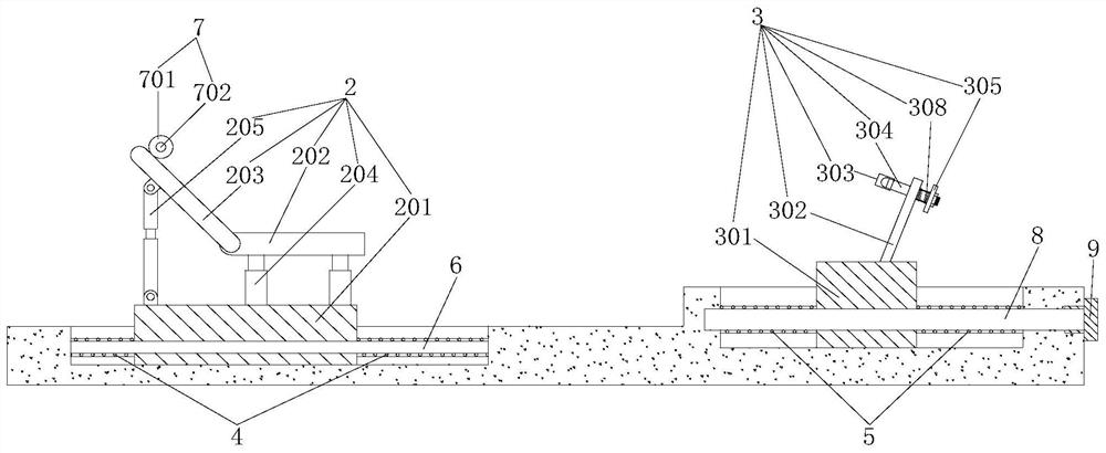
[0027] like figure 1 and figure 2 As shown, the present embodiment provides an orthopedic care traction bracket, comprising a base 1, a sliding seat mechanism 2 and a footstep traction mechanism 3, the upper end of the base 1 is provided with a first chute 101 and a second chute 102; the sliding The seat mechanism 2 is slidably connected in the first chute 101 with adjustable height, and the first elastic member 4 is arranged in the first chute 101, which is convenient for adjusting the sliding seat mechanism 2 and the foot traction mechanism through the first elastic member 4 3; the footstep traction mechanism 3 is slidably connected to the second chute 102, and the second chute 102 is provided with a second elastic member 5, which facilitates the adjustment of the footstep traction mechanism 3 and the adjustment of the footstep traction mechanism 3 through the second elastic member 5 The spacing between the sliding seat mechanisms 2.
[0028] The structure of the present ...
Embodiment 2
[0030] This embodiment is a further improvement made on the basis of Embodiment 1. The specific differences between this embodiment and Embodiment 1 are:
[0031] What needs to be further explained in this embodiment is that a first slide bar 6 is installed in the first chute 101, and the sliding seat mechanism 2 is slidably connected to the first slide bar 6, and the first slide bar 6 also serves as a sliding seat. A limit of the chair mechanism 2 controls the movement direction of the sliding seat mechanism 2; both sides of the sliding seat mechanism 2 are provided with first elastic members 4, and the two ends of each first elastic member 4 are respectively connected to The sliding seat mechanism 2 abuts against the inner wall of the first chute 101, and no matter which side the sliding seat mechanism 2 moves to, it will compress the corresponding first elastic member 4. In the absence of external force, the compressed first The elastic member 4 will drive the sliding seat ...
Embodiment 3
[0033] This embodiment is a further improvement made on the basis of Embodiment 2. The specific differences between this embodiment and Embodiment 2 are:
[0034]What needs to be further explained in this embodiment is that the sliding seat mechanism 2 includes a first slider 201 and a seat board 202 and a back board 203 arranged above the first slider 201, and the first slider 201 is slidably connected to On the first slide bar 6, the movement of the whole sliding seat mechanism 2 in the first chute is guaranteed, and the seat plate 202 is connected with the first slide block 201 through a plurality of first telescopic mechanisms 204, and returns when people sit on it. With certain adjustments, it is convenient to adjust according to the weight of the person, and the comfort is stronger; the leaning plate 203 is set at an inclination, such as figure 1 As shown, and the lower end of the back board 203 is hinged with the end of the seat board 202 away from the foot traction mec...
PUM
 Abstract
Description
Claims
Application Information
 - R&D
- Intellectual Property
- Life Sciences
- Materials
- Tech Scout
- Unparalleled Data Quality
- Higher Quality Content
- 60% Fewer Hallucinations
Browse by: Latest US Patents, China's latest patents, Technical Efficacy Thesaurus, Application Domain, Technology Topic, Popular Technical Reports.
© 2025 PatSnap. All rights reserved.Legal|Privacy policy|Modern Slavery Act Transparency Statement|Sitemap|About US| Contact US: help@patsnap.com