Harmful gas treatment system for metal material hot working

A technology of harmful gases and metal materials, applied in indirect heat exchangers, heat exchanger types, lighting and heating equipment, etc., can solve the problems of inhomogeneous catalyst addition, high temperature of harmful gases, inconvenient direct treatment and discharge, etc.

Inactive Publication Date: 2020-10-23
罗峰
View PDF4 Cites 4 Cited by
  • Summary
  • Abstract
  • Description
  • Claims
  • Application Information

AI Technical Summary

Problems solved by technology

[0004] The purpose of the present invention is to solve the problem that it is inconvenient to filter a large amount of dust in the harmful gas in advance when the harmful gas treatment device in the prior art is in use, and the temperature of the newly generated harmful gas is too high to be convenient for direct treatment and Disadvantages of emission and inability to uniformly add catalysts, and a harmful gas treatment system for thermal processing of metal materials is proposed

Method used


Image

  • Harmful gas treatment system for metal material hot working
  • Harmful gas treatment system for metal material hot working
  • Harmful gas treatment system for metal material hot working

Examples


Embodiment 1

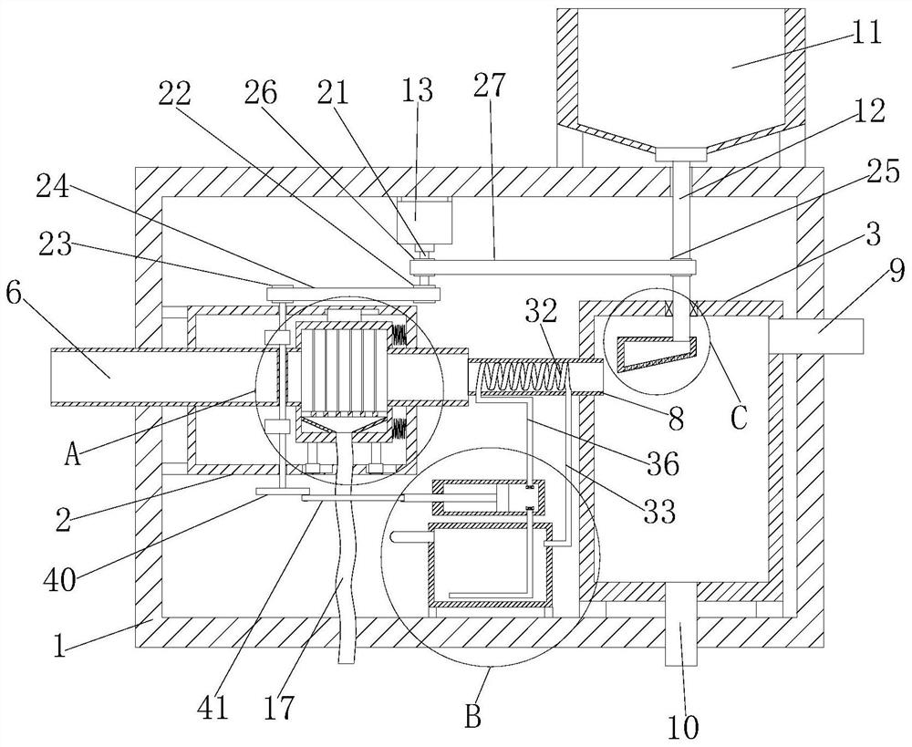
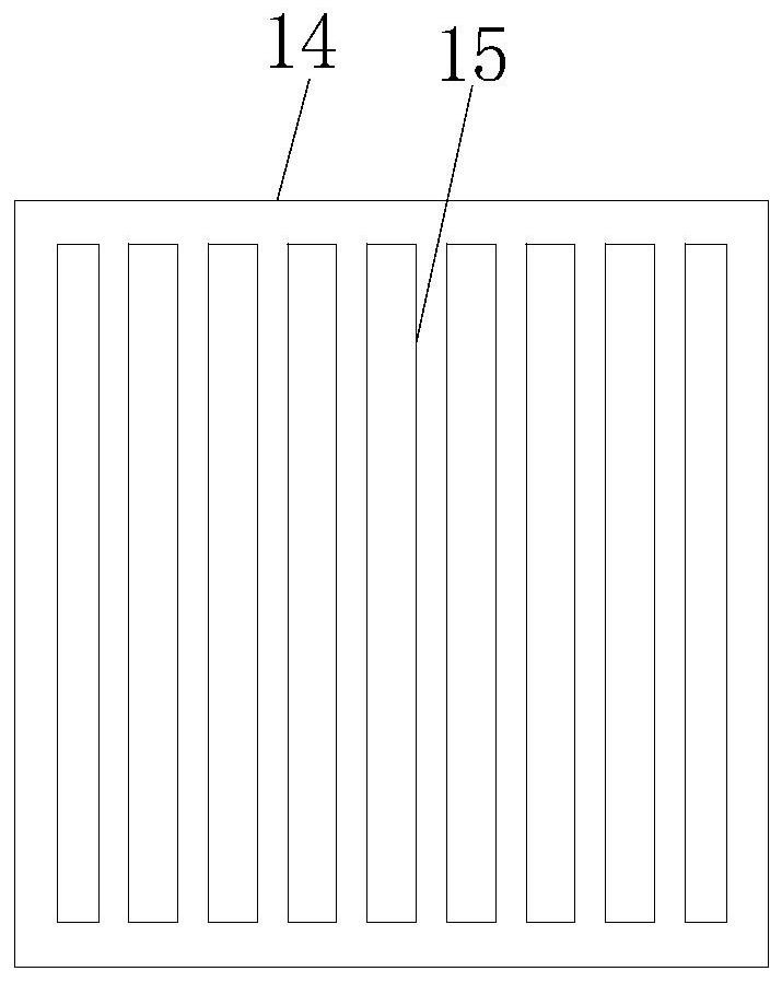
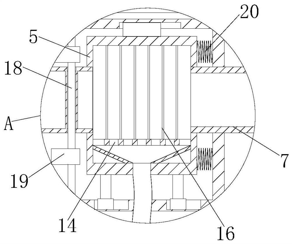
[0029] Reference Figure 1-5 , A harmful gas treatment system for thermal processing of metal materials, comprising a housing 1, a first dust removal housing 2 and a purification housing 3 and a water tank 4 are fixedly installed in the housing 1, and the first dust removal housing 2 is slidably installed The second dust removal housing 5, one side of the second dust removal housing 5 is connected with one end of the air inlet pipe 6, the other end of the air inlet pipe 6 penetrates the first dust removal housing 2 and the housing 1, and the second dust removal housing 5 One end of the first air outlet pipe 7 is connected to the other side, and the other end of the first air outlet pipe 7 extends through the first dust removal housing 2 into the housing 1 and is connected to one end of the second air outlet pipe 8. The other end of the air pipe 8 is connected to one side of the purification housing 3, and the other side of the purification housing 3 is connected to one end of a...

Embodiment 2

[0040] Refer to Figure 1-5 , A hazardous gas treatment system for thermal processing of metal materials, comprising a housing 1, in which a first dust removal housing 2 and a purification housing 3 and a water tank 4 are fixedly installed by bolts, and the first dust removal housing 2 slides A second dust removal housing 5 is installed, one side of the second dust removal housing 5 is connected to one end of the air inlet pipe 6, and the other end of the air inlet pipe 6 penetrates the first dust removal housing 2 and the housing 1, and the second dust removal housing One end of the first air outlet pipe 7 is connected to the other side of 5, and the other end of the first air outlet pipe 7 extends through the first dust removal housing 2 into the housing 1 and is connected to one end of the second air outlet pipe 8. The other end of the two air outlet pipes 8 is connected to one side of the purification housing 3, the other side of the purification housing 3 is connected to o...


PUM


Abstract

The invention belongs to the technical field of harmful gas treatment, and especially relates to a harmful gas treatment system for metal material hot working. The harmful gas treatment system is provided to solve the problems that when existing harmful gas treatment devices are used, a large amount of dust in harmful gas is inconvenient to filter in advance, harmful gas which is just generated istoo high in temperature and is inconvenient to directly treat and discharge. The system comprises a shell, a first dust removal shell, a purification shell and a water tank are installed in the shell, a second dust removal shell is installed in the first dust removal shell, one side of the second dust removal shell is communicated with one end of a gas inlet pipe, the other end of the gas inlet pipe penetrates through the first dust removal shell and the shell, and the other side of the second dust removal shell is communicated with one end of a first gas outlet pipe. When the system is used,a large amount of dust in harmful gas can be filtered in advance, the harmful gas with over-high temperature is cooled, catalytic reaction and low-temperature gas emission are facilitated, and a catalyst can be uniformly added.

Description

Technical field [0001] The invention belongs to the technical field of hazardous gas treatment, and in particular relates to a hazardous gas treatment system for thermal processing of metal materials. Background technique [0002] Metal hot processing generally refers to work such as casting, forging, welding and heat treatment. It is characterized by high temperature, harmful gas, dust and noise in the production process, bad working conditions, personal injury accidents, and harmful gases that are not treated. Direct emissions can cause great harm to the health of workers and the environment, and various types of catalysts are usually used to catalytically treat different harmful gases. [0003] However, when the existing harmful gas treatment device is in use, it is inconvenient to pre-filter a large amount of dust in the harmful gas, and the temperature of the harmful gas just generated is too high to be directly processed and discharged, and the catalyst cannot be uniformly pr...

Claims


Application Information

Patent Timeline
Patent Type & Authority Applications(China)
IPC IPC(8): B01D46/02B01D46/04B01D53/88F28D7/02F28B1/02
CPCB01D46/023B01D46/04B01D53/885F28B1/02F28D7/024
Inventor 罗峰
Owner 罗峰
Why Eureka
Try Eureka