3D printing sand mould

A 3D printing and sand molding technology, which is applied in the field of 3D printing sand molding, can solve the problems of unable to print large sand molds as a whole, and the parting surface running out of fire.

Pending Publication Date: 2020-10-23
INST OF MACHINERY MFG TECH CHINA ACAD OF ENG PHYSICS
View PDF0 Cites 1 Cited by
  • Summary
  • Abstract
  • Description
  • Claims
  • Application Information

AI Technical Summary

Problems solved by technology

Limited by the size of the 3D printing equipment, it is impossible to print large sand molds as a whole. It needs to be divided into several parts and assembled
The sand mold assembled in blocks is easy to run out of fire at the parting surface because there is no protection of the traditional casting sand box

Method used


Image

  • 3D printing sand mould
  • 3D printing sand mould
  • 3D printing sand mould

Examples


Embodiment 1

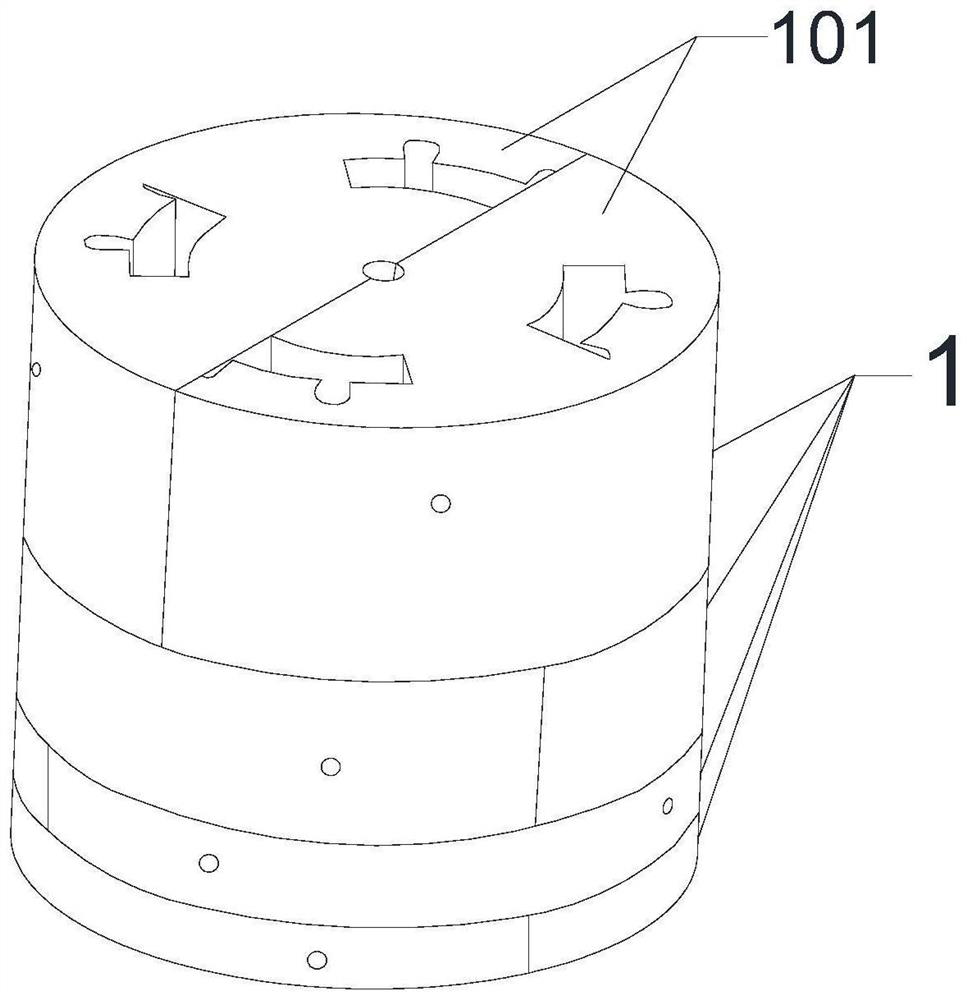
[0045] This embodiment provides a 3D printing sand mold, which is cylindrical as a whole, such as figure 1As shown, it includes four layers of transverse sand blocks 1, and the four layers of transverse sand blocks 1 are stacked up and down in sequence; wherein, the contact surface between the upper and lower adjacent layers of transverse sand blocks 1 is the transverse parting surface. Each horizontal sand mold block 1 includes two vertical sand mold blocks 101, and the contact surface between two adjacent vertical sand mold blocks 101 is a longitudinal parting surface, and the longitudinal parting surface and the transverse parting surface are perpendicular to each other. . And the longitudinal parting surface passes through the geometric center of the transverse sand mold block 1; the longitudinal parting surfaces on two adjacent layers of transverse sand mold blocks 1 are mutually misaligned. In the circumferential direction, the angle at which the vertical parting surfac...

Embodiment 3

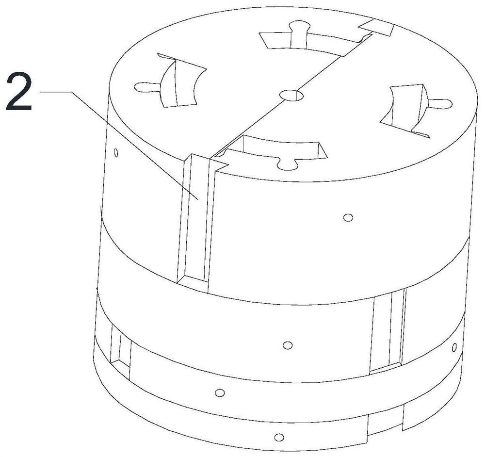
[0047] Further improvement on the basis of Example 2, a reserved groove 2 is provided at the outer slit of the longitudinal parting surface, and the outer boundary of the longitudinal parting surface is located at the bottom of the reserved groove 2; after the box is closed, The reserved groove 2 is used for filling clay sand or resin sand. The notch width of the reserved groove 2 is smaller than the width of the groove. In this embodiment, preferably, the reserved groove 2 has an isosceles trapezoidal structure on the cross section in the width direction of the reserved groove 2 .

Embodiment 4

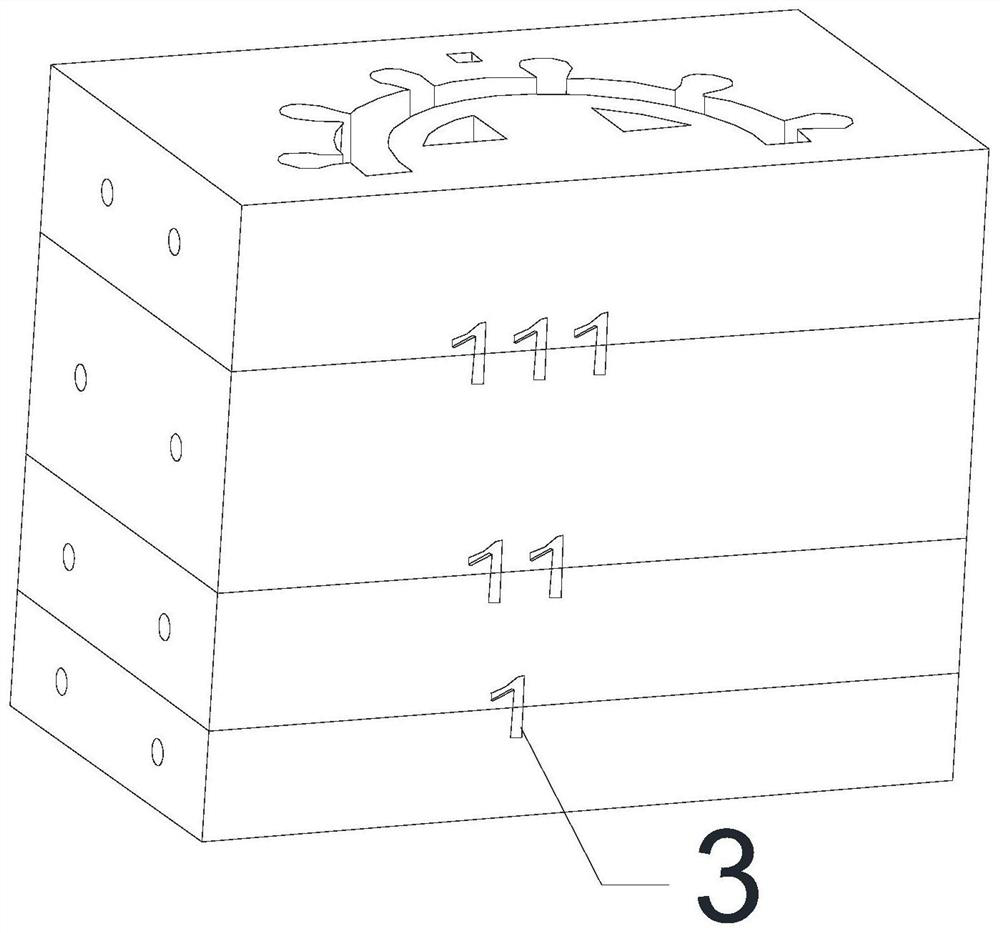
[0049] Further improvement on the basis of Example 3, positioning pins and positioning holes are respectively provided on the parting surfaces of the upper and lower adjacent horizontal sand blocks 1, and the positioning pins on the parting surface of one transverse sand block 1 are embedded in the adjacent Fit in the positioning hole on the parting surface of the transverse parting block 1. The circumferential gap between the positioning pin and the positioning hole is 1 mm, and the axial gap is 1 mm. Positioning holes or positioning pins are arranged on the transverse sand molding blocks 1 of the same layer, that is, the positioning types provided on the transverse sand molding blocks 1 of the same layer are the same.

[0050] Further preferably, the positioning number 3 is set on the side wall of the lateral sand molding block 1 of the adjacent layer, and the positioning number 3 runs through the upper and lower adjacent layers of the lateral sand molding blocks 1, such as ...


PUM

PropertyMeasurementUnit
lengthaaaaaaaaaa
diameteraaaaaaaaaa

Abstract

The invention discloses a 3D printing sand mould which comprises N layers of transverse sand mould blocks sequentially arranged up and down in a stacking manner; a contact surface between two upper and lower adjacent layers of transverse sand mould block is a transverse parting surface; N is a positive integer equal to or greater than 2; each layer of transverse sand mould blocks comprises M longitudinal sand mould sub blocks; a contact surface between two adjacent longitudinal sand mould sub blocks is a longitudinal parting surface; the longitudinal parting surface is perpendicular to the transverse parting surface; M is a positive integer equal to or greater than 2; a reserved groove is formed in the side walls, corresponding to the outer side gap of the longitudinal parting surface, ofthe two longitudinal sand mould sub blocks; the outer side gap of the longitudinal parting surface is positioned in the bottom of the reserved groove; after mould assembling, the reserved groove is used for being filled with clay sand or resin sand; and the longitudinal parting surfaces of two adjacent layers of transverse sand mould blocks are distributed in a staggered manner. According to the technical conception, through improving the sub block structure, sand removal, chill placing and assembling are facilitated, and runout is avoided.

Description

technical field [0001] The invention relates to the technical field of sand mold 3D printing, in particular to a 3D printing sand mold. Background technique [0002] Sand mold 3D printing technology has the advantages of short manufacturing cycle, digital production process, and no dust, etc. It is mainly used for the preparation of complex sand cores. Limited by the size of the 3D printing equipment, it is impossible to print a large sand mold as a whole, and it needs to be divided into several parts and assembled. Since the sand mold assembled in blocks is not protected by the traditional casting sand box, it is very easy to run out of fire at the parting surface. [0003] Therefore, how to design, which can not only facilitate sand cleaning and cold iron placement, but also facilitate assembly and avoid fire escape is the key to the application of sand mold 3D printing technology to large castings. Contents of the invention [0004] The technical problem to be solved ...

Claims


Application Information

Patent Timeline
Patent Type & Authority Applications(China)
IPC IPC(8): B22C9/02B33Y80/00
CPCB22C9/02B33Y80/00
Inventor 贾如刘建辉杨才良李凤春吴免向志刚
Owner INST OF MACHINERY MFG TECH CHINA ACAD OF ENG PHYSICS
Why Eureka
Try Eureka