Assembly device for charger shell production

A technology for assembling equipment and chargers, which is applied to metal processing equipment, metal processing, manufacturing tools, etc., and can solve problems such as easy to produce defective products and poor accuracy

Inactive Publication Date: 2020-10-23
长兴梦晨节能设备有限公司
View PDF0 Cites 2 Cited by
  • Summary
  • Abstract
  • Description
  • Claims
  • Application Information

AI Technical Summary

Problems solved by technology

[0005] The purpose of the present invention is to address the deficiencies of the prior art, by setting the plug transmission mechanism and the casing transmission mechanism to realize the automatic sequential loading of the casing and the plug, and at the same time using the automatic assembly mechanism to precisely position the casing and the plug and integrate them into one Compression molding, automatic extraction and output after the finished product is formed, at the same time avoiding damage to the shell and plug during manual assembly, improving product quality, thereby solving the need for manual two-handed simultaneous operation to place the charger shell, and poor alignment accuracy. Technical problems prone to defective products

Method used


Image

  • Assembly device for charger shell production
  • Assembly device for charger shell production
  • Assembly device for charger shell production

Examples


Embodiment 1

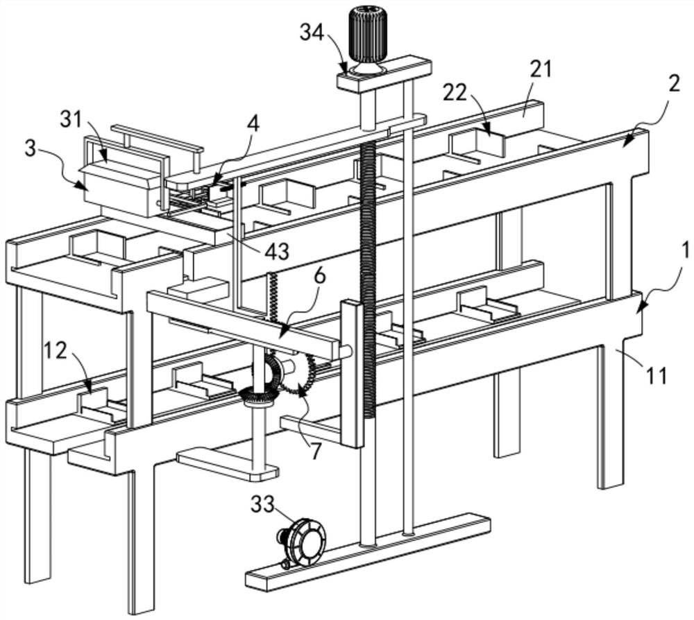
[0063] Such as figure 1 and figure 2 As shown, an assembly equipment for the production of a charger shell, including:

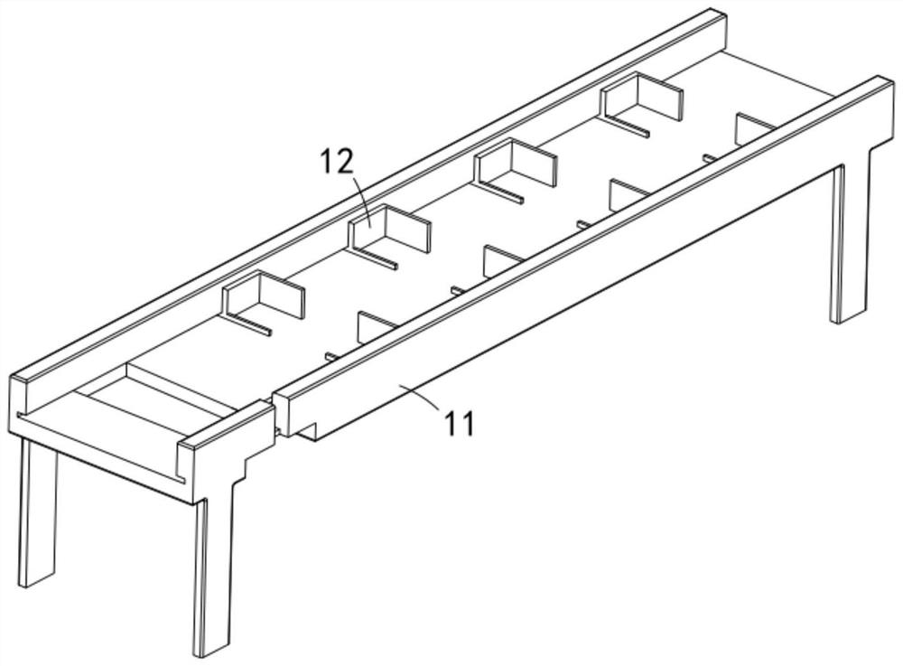
[0064] A plug transmission mechanism 1, the plug transmission mechanism 1 includes a transmission track a11 and several sets of receiving plates a12 that are matched and slidably arranged on the transmission track a11 at equal intervals;

[0065] The housing transmission mechanism 2, the housing transmission mechanism 2 is arranged above the plug transmission mechanism 1, and includes a transmission track b21 and several sets of receiving plates b22 equidistantly matching and slidingly arranged on the transmission track b21;

[0066] An automatic assembly mechanism 3, the automatic assembly mechanism 3 is located at the assembly station, and the automatic assembly mechanism 3 includes a first adsorption assembly 31 located below the plug transmission mechanism 1, a second adsorption assembly 31 arranged above the housing transmission mechanism 2 The adsor...

Embodiment 2

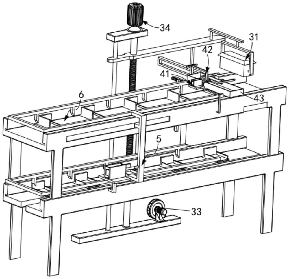
[0101] Such as Figure 13 , Figure 14 As shown, the parts that are the same as or corresponding to those in the first embodiment are marked with the corresponding reference numerals in the first embodiment. For the sake of simplicity, only the differences from the first embodiment are described below. The difference between this embodiment two and embodiment one is:

[0102] further, such as Figure 13 , Figure 14 As shown, the horizontal pushing assembly 6 includes:

[0103] A flat plate 61, the flat plate 61 is matched and engaged in the transmission track b21;

[0104] A connecting frame 62, the connecting frame 62 is fixedly connected to the moving end of the flat panel 61; and

[0105] The limiting track 63 is provided with a telescopic unit 64 inside the limiting track 63 , and the telescopic unit 64 is fixedly connected with the connecting frame 62 .

[0106] In this embodiment, by setting the horizontal pushing assembly 6 to cooperate with the first transmissio...


PUM


Abstract

The invention relates to an assembly device for charger shell production. The assembly device comprises a plug conveying mechanism, a shell conveying mechanism, an automatic assembly mechanism and a finished product discharging mechanism, wherein the plug conveying mechanism comprises a conveying track a and a bearing plate a; the shell conveying mechanism is arranged above the plug conveying mechanism and comprises a conveying track b and a bearing plate b; the automatic assembly mechanism is positioned at an assembly station and comprises a first adsorption assembly, a second adsorption assembly, a vacuum pump and a lifting assembly; the finished product discharging mechanism comprises a stripping assembly, a control assembly and a collecting box; the shell conveying mechanism and the plug conveying mechanism realize intermittent movement of the bearing plate a and the bearing plate b towards the output end of the shell conveying mechanism through a driving mechanism; and a horizontal pushing assembly is arranged at the assembly station, penetrates through the conveying track b and is in smooth transition connection with the conveying track b. The assembly device solves the technical problems that charger shells need to be placed manually by two hands at the same time, in addition, the alignment precision is poor, and defective products are prone to being generated.

Description

technical field [0001] The invention relates to the technical field of charger shells, in particular to an assembly equipment for the production of charger shells. Background technique [0002] The charger is a device for charging the energy storage module. In today's environment where electronic products are widely used, the charger is widely used. During the production process, when the shell is assembled, the traditional method is manual Therefore, it is easy to cause wear and tear on the charger shell during the assembly process of the charger. To this end, we propose an assembly facility for charger production. [0003] The patent document with the patent number CN2017216386504 discloses a kind of assembly equipment for charger production, including a support seat, one end of the upper surface of the support seat is provided with a first rotating seat, and the first rotating seat is provided with a vertically upward threaded rod. The upper end of the rod is provided w...

Claims


Application Information

Patent Timeline
Patent Type & Authority Applications(China)
IPC IPC(8): B23P19/027B23P19/00
CPCB23P19/00B23P19/001B23P19/027
Inventor 史强大
Owner 长兴梦晨节能设备有限公司
Why Eureka
Try Eureka