Low-voltage switch drawer cable clamp spring replacement device and method

A low-voltage switch and circlip technology, which is applied in the field of low-voltage switch drawer cable circlip replacement devices, can solve the problems of inability to guarantee the clamping force of a primary circuit connector, failure to meet inspection standards, and inconvenient operation.

Pending Publication Date: 2020-10-23
JIANGSU NUCLEAR POWER CORP
View PDF0 Cites 0 Cited by
  • Summary
  • Abstract
  • Description
  • Claims
  • Application Information

AI Technical Summary

Problems solved by technology

[0002] Most of the bus bars of a nuclear power plant unit use low-voltage switchgear drawers with a height of 8E (1E=25mm) or more. During the process of testing the clamping force of the primary circuit connectors of the drawers, the following problems were found: (1) For the primary circuit plugging of 8E and above drawers Most of the connectors of the connectors are MNS2.0, and the qualified standard is 73N. However, it is found that some cable primary circuit connectors do not meet the inspection standards due to long-term online use; (2) if the primary circuit of the switch drawer When the cable with insufficient clamping force of the connector is replaced, the staff needs to modify the new cable to make it consistent with the length of the on-site cable, and the joint needs to be re-pressed. The process is complicated, time-consuming and labor-intensive.
Moreover, the internal space of the drawer is small, and the operation is inconvenient for replacement; (3) If the clamping spring is replaced for the cable with insufficient clamping force of the primary circuit connector of the switch drawer, because there is no special tool, usually only needle-nose pliers can be used to replace it. The new snap ring cannot be installed in place at one time, and the clamping force of the primary circuit connector after replacement cannot be guaranteed

Method used


Image

  • Low-voltage switch drawer cable clamp spring replacement device and method

Examples


Embodiment Construction

[0026] Below in conjunction with embodiment and accompanying drawing, the present invention is further described:

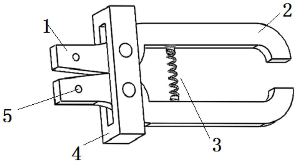
[0027] Such as figure 1 As shown, the present invention provides a low-voltage switch drawer cable clamp replacement device, which includes a clamp body 1, a handle 2, a spring 3, a handle support block 4 and a cylindrical protrusion 5.

[0028] The two caliper bodies 1 are fixedly connected with the two handles 2 respectively through the handle support block 4 and the pin, and the spring 3 is fixedly connected in the middle of the two handles 2 with the pin, so that the circlip replacement device is assembled into a whole.

[0029] The clamp body 1 is made of stainless steel.

[0030] A cylindrical protrusion 5 is provided on the surface of the pliers body 1, and the cylindrical protrusion 5 is firmly connected with the circlip, so that the circlip can be quickly removed and reinstalled.

[0031] The tail of the pliers body 1 is circular.

[0032] Spring 3 pl...


PUM


Abstract

The invention belongs to the technical field of nuclear power station electrical maintenance and particularly relates to a low-voltage switch drawer cable clamp spring replacement device and method. The device comprises clamp bodies, handles and a spring, wherein the two clamp bodies are fixedly connected with the two handles respectively, and the spring is connected between the two handles. According to the low-voltage switch drawer cable clamp spring replacement device and method, the increase of the workload caused by the modification of a primary loop plug-in of a cable by a worker on thescene is avoided, the cost is saved, the material waste is reduced, the working efficiency is improved, the clamping force of the primary loop plug-in of a drawer after replacement is greatly improved, and the inspection standard is met; and the spring is arranged close to the handles, so that a certain resilience force is ensured, the use by the worker is facilitated, and the device is convenientto carry to a field for use.

Description

technical field [0001] The invention belongs to the technical field of nuclear power plant electrical maintenance, and in particular relates to a device and method for replacing a cable clip spring of a low-voltage switch drawer. Background technique [0002] Most of the bus bars of a nuclear power plant unit use low-voltage switchgear drawers with a height of 8E (1E=25mm) or more. During the process of testing the clamping force of the primary circuit connectors of the drawers, the following problems were found: (1) For the primary circuit plugging of 8E and above drawers Most of the connectors of the connectors are MNS2.0, and the qualified standard is 73N. However, it is found that some cable primary circuit connectors do not meet the inspection standards due to long-term online use; (2) if the primary circuit of the switch drawer When the cable with insufficient clamping force of the connector is replaced, the staff needs to modify the new cable to make it the same lengt...

Claims


Application Information

Patent Timeline
IPC IPC(8): B25B27/30H02B3/00H02G1/00
CPCB25B27/30H02B3/00H02G1/00
Inventor 武传张双强张雅文王昊徐广建黄巍华王雄辉郭鑫罗德志司旭东黄进伟杨亚松张睿
Owner JIANGSU NUCLEAR POWER CORP
Why Eureka
Try Eureka