Supercharge Your Innovation With Domain-Expert AI Agents!

Tower crane luffing trolley motor replacement device and replacement method

A technology of luffing trolley and tower crane, which is applied in cranes, transportation and packaging, etc. It can solve the problems of poor suspension of seat belts, no better solution, and high labor intensity, so as to reduce on-site work coordination time and accurately control maintenance Time, the effect of reducing the risk of working at heights

Active Publication Date: 2022-04-15
CHINA HUAYE GROUP
View PDF9 Cites 0 Cited by
  • Summary
  • Abstract
  • Description
  • Claims
  • Application Information

AI Technical Summary

Problems solved by technology

[0005] Three people removed the old motor and lifted it to the junction of the boom and the tower body, put the old motor on the jacking platform with a chain hoist, and hoisted the new motor to the junction of the boom and the tower body. Lift the luffing motor on the boom track to the position of the luffing hoist (two people are needed to hold the boom with one hand and lift the motor with the other, because there are too many people to lift the motor when walking on the boom track. Uniform, unsynchronized actions, poor coordination with each other, prone to accidents, and the seat belt is not easy to hang)
Moreover, the motor is heavy. If you need to stop and rest when lifting the motor, the motor will not be stable when placed on the boom track.
Especially when installing the motor, the operation space is small, so it should be operated by three people (two people lift the motor, one person is responsible for the insertion of the motor shaft), the angle adjustment is time-consuming and laborious, the operation is difficult and labor-intensive
[0006] For the above problems, there is no better solution

Method used


Image

  • Tower crane luffing trolley motor replacement device and replacement method
  • Tower crane luffing trolley motor replacement device and replacement method
  • Tower crane luffing trolley motor replacement device and replacement method

Examples


Embodiment Construction

[0039] Embodiments of the motor replacement device and replacement method for the luffing trolley of the tower crane according to the present invention will be described below with reference to the accompanying drawings. Those skilled in the art would recognize that the described embodiments can be modified in various ways or combinations thereof without departing from the spirit and scope of the invention. Accordingly, the drawings and description are illustrative in nature and not intended to limit the scope of the claims. Also, in this specification, the drawings are not drawn to scale, and like reference numerals denote like parts.

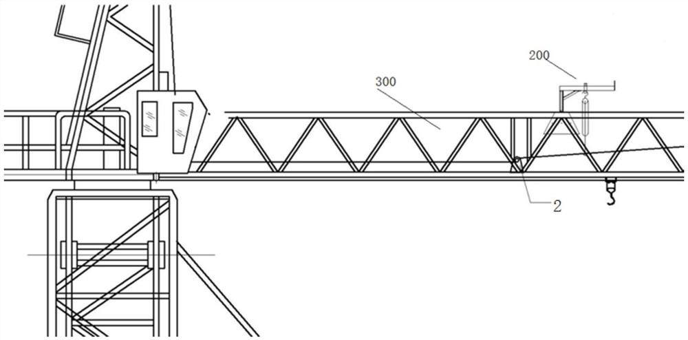
[0040]The tower crane luffing trolley motor replacement device 200 includes a support part 6, a turning part and a suspension part, wherein the support part 6 is arranged on the upper end of the boom 300 in a form adapted to the shape of the upper end of the boom 300, for example, the cross section is triangular The boom 300 includes two lowe...


PUM


Abstract

The invention provides a tower crane luffing trolley motor replacement device and a replacement method. The device includes: a supporting part, including a top plate, and the top plate is fixed on the upper end of the upper chord of the boom; The rotary sleeve on the outer periphery of the vertical shaft allows the suspension part to rotate around the vertical shaft; the suspension part includes a suspension arm, the end of the suspension arm is fixedly connected to the upper end of the rotary sleeve, and the other end of the suspension arm is provided with a baffle, The two connecting plates are symmetrically arranged on both sides of the suspension arm in the width direction. Two pin holes are arranged vertically at intervals on the two connecting plates. The pin shaft passing through the pin holes on the upper part of the connecting plate installs the pulley on the suspension The upper end of the arm, the pin shaft passing through the pin hole at the bottom of the connecting plate is used as the hanging point of the chain; the upper hook of the chain is hung on the hanging point when the chain is reversed. In the present invention, one person can complete the maintenance work of the motor, and the motor can be removed and installed at 360 degrees without dead angle by utilizing the rotation of the suspension arm, the sliding of the pulley, and the lifting and lowering of the reverse chain.

Description

technical field [0001] The invention relates to the technical field of building construction, in particular to a motor replacement device and replacement method for a luffing trolley of a tower crane. Background technique [0002] The tower crane includes booms and balance arms on both sides of the tower body, and the luffing motor 2 of the tower crane is used to pull the trolley on the boom to move along the boom (big arm) 300 of the tower crane, such as figure 2 As shown, the motor 2 transmits power through the wire rope coiled on the drum 3 of the luffing machine. The luffing motor 2 is installed on the boom and away from the control room. Usually, the luffing motor 2 is about 6-10 meters away from the tower body of the tower crane. The installation position is as follows: figure 1 shown. In the use of tower cranes, most of the buildings are high-rise or super-high-rise buildings. When the luffing motor burns out and replaces or breaks down and is removed for maintenan...

Claims


Application Information

Patent Timeline
Patent Type & Authority Patents(China)
IPC IPC(8): B66C23/16B66C23/78B66C23/84B66C23/88
CPCB66C23/163B66C23/78B66C23/88B66C23/84B66C2700/03
Inventor 闻忠振孙海滨张荣锦
Owner CHINA HUAYE GROUP
Features
  • R&D
  • Intellectual Property
  • Life Sciences
  • Materials
  • Tech Scout
  • Unparalleled Data Quality
  • Higher Quality Content
  • 60% Fewer Hallucinations
Learn More