Air-entrained anti-cavitation structure behind the gate of flood discharge tunnel

A technology of flood discharge tunnels and gates, which is applied in hydropower stations, coastline protection, sea area engineering, etc., can solve problems such as unsatisfactory protection of aerated facilities, damage to flood discharge projects, and threats to project safety, so as to avoid cavitation damage, The effect of prolonging the service life and ensuring the safety of the structure

Active Publication Date: 2022-02-11
CHINA POWER CONSRTUCTION GRP GUIYANG SURVEY & DESIGN INST CO LTD
View PDF0 Cites 2 Cited by
  • Summary
  • Abstract
  • Description
  • Claims
  • Application Information

AI Technical Summary

Problems solved by technology

At present, aerated facilities are mostly used to prevent cavitation and cavitation erosion of high-speed water flow, but aerated facilities often fail to play a good protective role due to unsatisfactory design
With the rapid development of high dam projects, the scale of discharge structures is getting larger and larger, and the flood discharge flow rate of some projects has exceeded 50m / s. Water flow cavitation damage behind the gates occurs from time to time, and conventional traditional anti-cavitation structures are difficult to meet the demand. , especially in the downstream of the flood discharge tunnel after the gate is installed, cavitation damage is very easy to occur, which will lead to the destruction of the entire flood discharge project and threaten the safety of the project

Method used


Image

  • Air-entrained anti-cavitation structure behind the gate of flood discharge tunnel
  • Air-entrained anti-cavitation structure behind the gate of flood discharge tunnel
  • Air-entrained anti-cavitation structure behind the gate of flood discharge tunnel

Examples


Embodiment Construction

[0019] The technical solution of the present invention is further described below, but the scope of protection is not limited to the description.

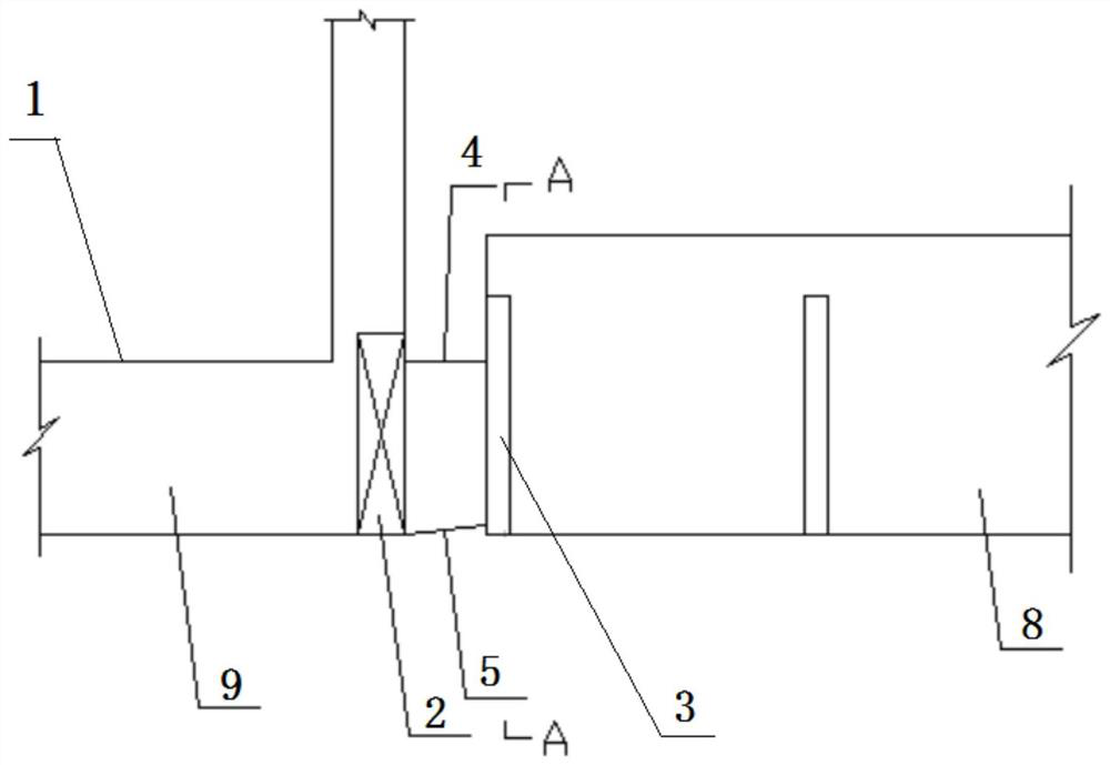
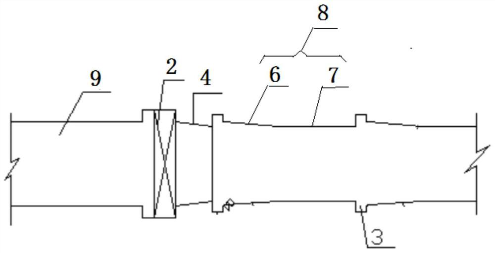
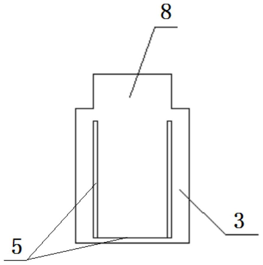
[0020] like figure 1 , figure 2 and image 3 As shown, an aerated anti-cavitation structure of a flood discharge tunnel gate of the present invention includes a flood discharge tunnel 1, a gate 2 is installed on the flood discharge tunnel 1, and at least one ventilation groove 3 is arranged downstream of the gate 2, and the ventilation groove 3 is connected with the external atmospheric environment. The flood discharge tunnel 1 between the gate 2 and the first ventilation groove 3 is a closed section 4, and a deflector 5 is arranged in the closed section 4.

[0021] Further, the deflector 5 is arranged at one or more of the left wall, the right wall and the bottom plate of the closed section 4 . Preferably, the slope of the floor deflector 5 is 1:10-1:30. The slope of the deflector 5 on the left wall or the right wall is 1:10-...


PUM


Abstract

The invention discloses an aerated anti-cavitation structure behind the gate of a flood discharge tunnel, comprising a flood discharge tunnel, on which a gate is installed, and at least one ventilation slot is arranged downstream of the gate, and the ventilation slot communicates with the external atmospheric environment, The flood discharge tunnel between the gate and the first ventilation slot is a closed section, and a deflector is arranged in the closed section. Adopting the technical solution of the present invention, by setting a closed section on the downstream flood discharge tunnel at the position where the gate is installed in the flood discharge tunnel, and setting a deflector in the closed end, the water flow forms a high-speed jet after flowing through the closed section, which speeds up the flow rate of the water flow, and By setting the venting groove connected to the atmospheric environment in the downstream unpressurized section of the closed section, aeration is performed on the jet flow, which effectively avoids cavitation damage to the flood discharge tunnel downstream of the gate, ensures the safety of water conservancy facilities, and prolongs the use of water conservancy facilities. life.

Description

technical field [0001] The invention relates to the technical field of water conservancy facilities engineering, in particular to an aerated anti-cavitation structure behind a gate of a flood discharge tunnel. Background technique [0002] The anti-cavitation design behind the floodgate gate of water conservancy and hydropower projects is a very important content. At present, aerated facilities are mostly used to prevent cavitation and cavitation erosion of high-speed water flow, but aerated facilities often fail to play a good protective role due to unsatisfactory design. With the rapid development of high dam projects, the scale of discharge structures is getting larger and larger, and the flood discharge flow rate of some projects has exceeded 50m / s. Water flow cavitation damage behind the gates occurs from time to time, and conventional traditional anti-cavitation structures are difficult to meet the demand. , especially in the downstream of the flood discharge tunnel a...

Claims


Application Information

Patent Timeline
Patent Type & Authority Patents(China)
IPC IPC(8): E02B8/06E02B8/00E02B9/06
CPCE02B8/06E02B8/00E02B9/06Y02E10/20
Inventor 郑雪玉彭浩黄叶飘鲍伟陈润泽
Owner CHINA POWER CONSRTUCTION GRP GUIYANG SURVEY & DESIGN INST CO LTD
Why Eureka
Try Eureka