
Flue construction method

A construction method and flue technology, applied to vertical pipes, building components, buildings, etc., can solve problems such as easy water seepage, hidden danger of leakage at the joint between the flue and concrete structure, and difficulty in installing the flue

Pending Publication Date: 2020-10-23
SHANDONG SANJIAN CONSTR ENG MANAGEMENT +1
View PDF3 Cites 1 Cited by
  • Summary
  • Abstract
  • Description
  • Claims
  • Application Information

AI Technical Summary

Problems solved by technology

There are certain technical and quality problems in this construction method in the prior art: there is a certain randomness in the installation of the steel support in the construction process, the steel support is not fixed, there are safety and quality problems of instability and instability, and there are flue ducts at the same time. Difficult installation, long flue installation and construction process, and because the flue is directly placed in the reserved hole, there is no effective anti-leakage facility between the flue and the surrounding concrete structure, resulting in the presence of stubble between the flue and the concrete structure. Hidden danger of leakage, easy to seepage, and the late leakage of this part leads to more complaints from the owners, time-consuming and labor-intensive maintenance, and it is difficult to achieve a satisfactory treatment effect in the post-processing

Method used


Image

  • Flue construction method
  • Flue construction method
  • Flue construction method

Examples


Embodiment Construction

[0021] The present invention will be further described below in conjunction with accompanying drawing by non-limiting embodiment:

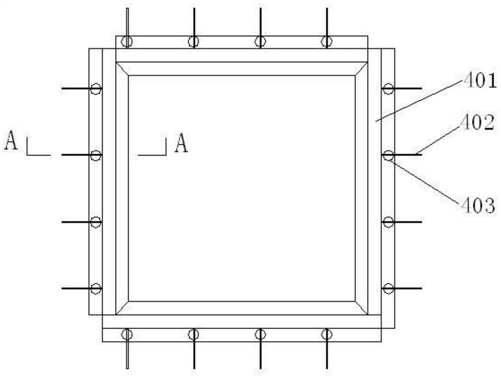
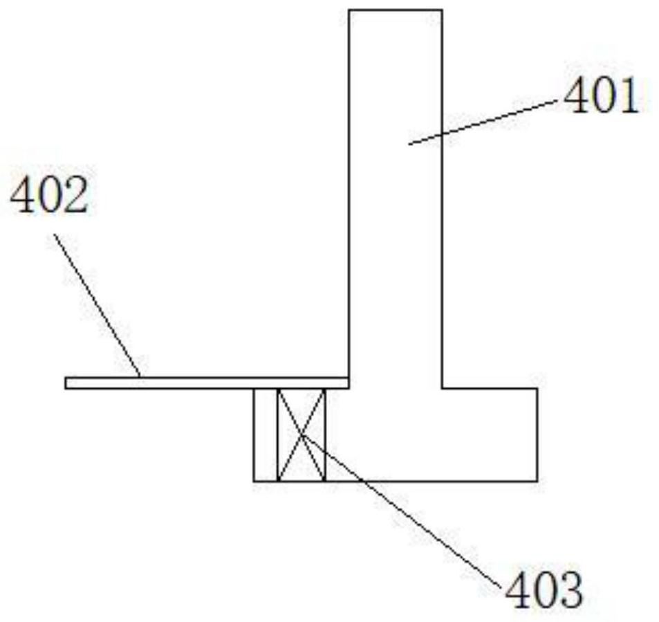
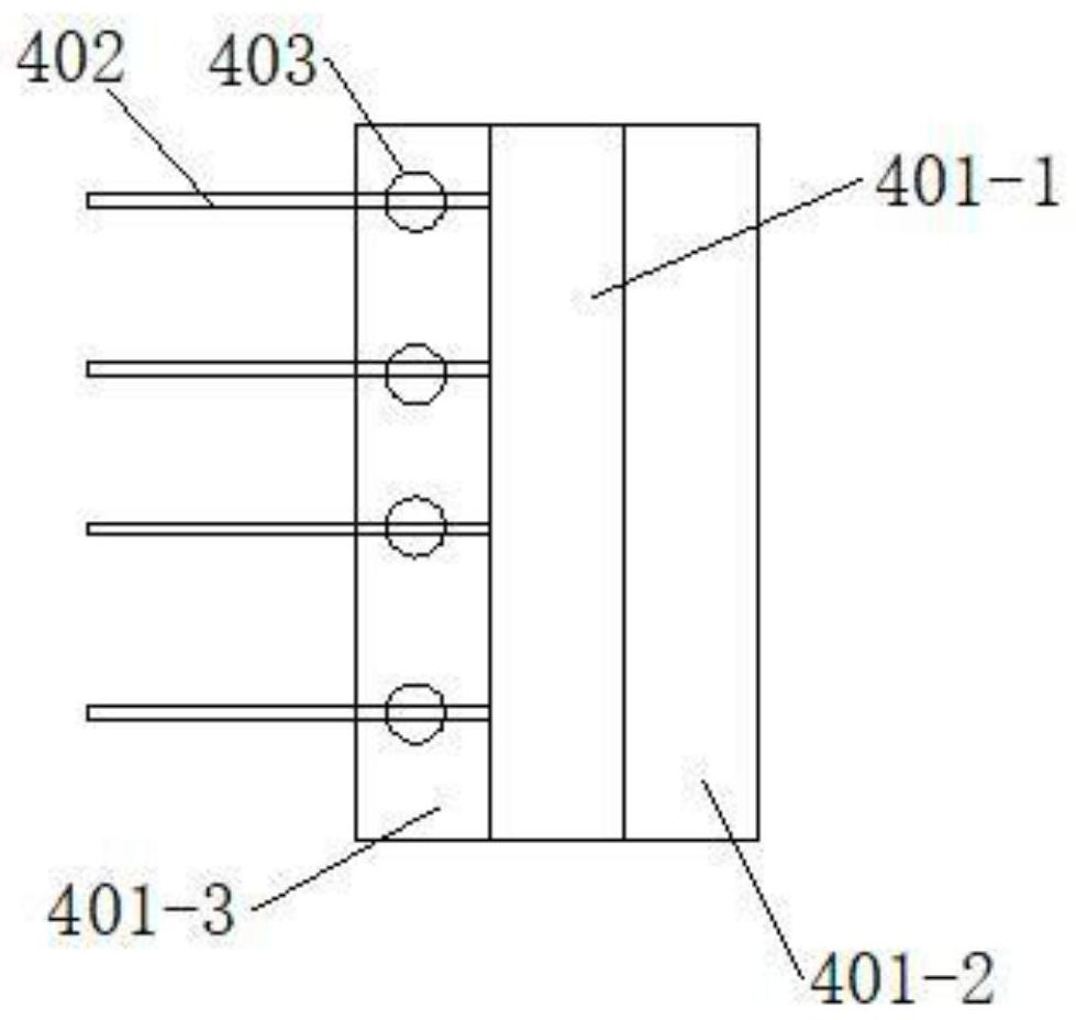
[0022] As shown in the accompanying drawings, a flue construction method uses a flue installation device 4 for construction. The flue installation device 4 includes a rectangular frame steel supporting member, and the four frames of the steel supporting member are composed of a T-shaped steel skeleton 401 in section. The cross-section of the steel frame 401 is T-shaped, including a web 401-1, an inner flange 401-2, and an outer flange 401-3. The steel frame 401 can be manufactured by plate welding. The webs 401-1 of the steel frame 401 of the four frames of the steel supporting member are connected to each other to form a rectangular web frame matching the cross-sectional size of the flue, and the four corners of the rectangular web frame are sealed and connected. Several through holes 403 are provided on the outer wing plate 401-3 of each steel ...


PUM


Abstract

The invention discloses a flue construction method. A flue mounting device is adopted for construction, the flue mounting device comprises a rectangular frame type steel bearing component, a frame ofthe steel bearing component is a steel framework with a T-shaped section, and a plurality of through holes are formed in outer side wing plates of the steel framework and a plurality of transverse anchoring steel bars are fixedly connected to the outer side wing plates of the steel framework; the construction method comprises the construction steps of welding the steel framework into a rectangularframe according to the design size of a flue; machining the through holes in the outer side wing plates of the steel framework, welding the anchoring steel bars according to the binding requirement,and completing the manufacturing of the flue mounting device; mounting the flue mounting device at the designed position of the flue, and binding and connecting the anchoring steel bars of the flue mounting device with floor steel bars and shear wall steel bars around the flue; pouring concrete, specifically, pouring the flue mounting device, a floor around the flue and a shear wall into a whole through the concrete; mounting a flue on the inner side of the flue mounting device; and carrying out waterproof and inlaying operations on the outer side of the flue mounting device.

Description

technical field [0001] The invention relates to a flue construction method, which belongs to the technical field of building construction. Background technique [0002] In the prior art, prefabricated parts are generally used for the flue, and the prefabricated flue is installed in place later. In the prior art, the installation method of the flue is to reserve a reserved hole for the flue on the building structure, place a steel support in the reserved hole for the flue during installation, support the flue through the steel support, and then perform the flue and Rigid sealing and waterproof detail treatment between structures to achieve the purpose of impermeability. There are certain technical and quality problems in this construction method in the prior art: there is a certain randomness in the installation of the steel support in the construction process, the steel support is not fixed, there are safety and quality problems of instability and instability, and there are...

Claims


Application Information

Patent Timeline
IPC IPC(8): E04F17/02E04B1/41
CPCE04B1/41E04F17/02
Inventor 杜加川李霖霖李振张如生刘伟陈岳敏田园园陈承壮唐宽好
Owner SHANDONG SANJIAN CONSTR ENG MANAGEMENT
Learn More