High-efficiency gas supply device for gas boiler

A gas-fired boiler, high-efficiency technology, applied to pump devices, components of pumping devices for elastic fluids, liquid fuel engines, etc., can solve the problems of gas-fired boilers lack of oxygen, time-consuming disassembly and assembly of fans, and easy adhesion

Active Publication Date: 2020-10-23
江苏迈阳环保有限公司
View PDF6 Cites 0 Cited by
  • Summary
  • Abstract
  • Description
  • Claims
  • Application Information

AI Technical Summary

Problems solved by technology

[0006] When the fan is used for a long time, the side of the blade that pushes the airflow is very likely to stick to the dust in the air and form accumulations. In order to prevent large pieces of ash from pouring into the gas boiler, the fan needs to be disassembled periodical

Method used


Image

  • High-efficiency gas supply device for gas boiler
  • High-efficiency gas supply device for gas boiler
  • High-efficiency gas supply device for gas boiler

Examples


Embodiment Construction

[0046] The present invention will be described in further detail below in conjunction with the accompanying drawings.

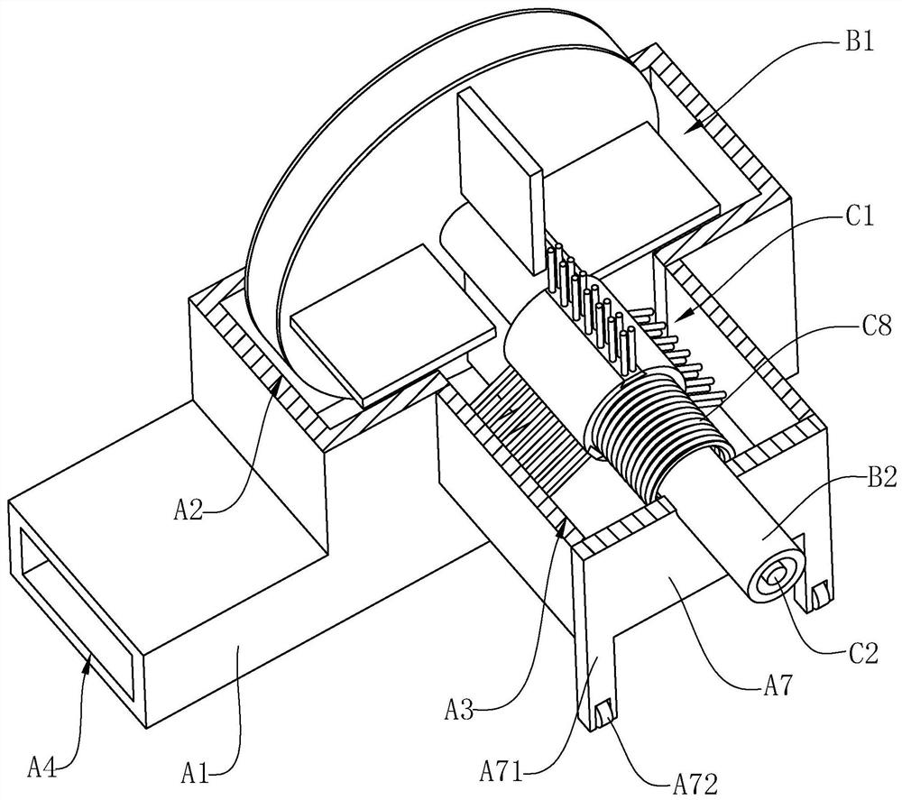
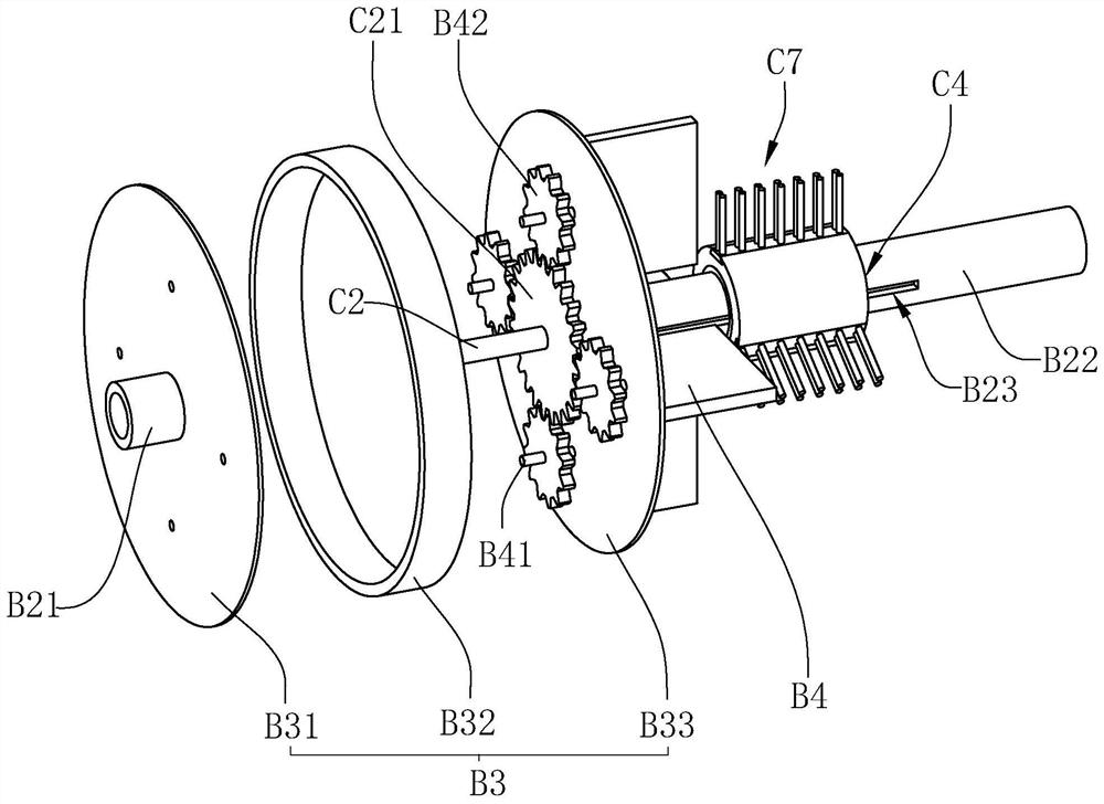
[0047] Such asfigure 1 with figure 2 As shown, a gas-fired boiler high-efficiency gas supply device includes a casing A1, an acceleration component B1 and a cleaning component C1. An acceleration chamber A2 and a storage cavity A3 are arranged in the casing A1. The acceleration chamber A2 communicates with the storage cavity A3, and the acceleration component B1 is rotated and installed in the acceleration chamber A2, and the cleaning component C1 is movably arranged in the acceleration chamber A2 and the storage chamber A3, and the housing A1 is also provided with an air inlet A4, an air outlet A5 and The second air outlet A6, wherein the first air outlet A5 and the second air outlet A6 are respectively provided with valves;

[0048] When the device is in the normal air supply state, the first air outlet A5 is opened and the second air outlet A6 is closed,...


PUM


Abstract

The invention relates to the technical field of fans, and discloses a high-efficiency gas supply device for a gas boiler. The high-efficiency gas supply device comprises a casing, an accelerating assembly and a cleaning assembly, wherein an accelerating cavity and a containing cavity are formed in the casing; the accelerating cavity communicates with the containing cavity; the accelerating assembly is rotationally arranged in the accelerating cavity; the cleaning assembly is movably arranged between the accelerating cavity and the containing cavity; and an air inlet, a first air outlet and a second air outlet communicating with the accelerating cavity are further formed in the casing, wherein valves are arranged in the first air outlet and the second air outlet respectively. When the device is in a shutdown cleaning state, the first air outlet is closed, the second air outlet is opened, the cleaning assembly moves from the containing cavity into the accelerating cavity, and the cleaning assembly cleans the accelerating assembly; and when the device is in a pollution discharge state, the first air outlet is closed, the second air outlet is opened, the cleaning assembly moves into the containing cavity again, and the accelerating assembly sends residual accumulated ash in the accelerating cavity out of the second air outlet through air flow, so that the purpose of quick ash removing is achieved.

Description

technical field [0001] The invention relates to the technical field of fans, in particular to a high-efficiency gas supply device for a gas boiler. Background technique [0002] A fan is a device that absorbs air from the outside, accelerates the air inside, and then sends it out. Among them, a fan is often needed in a large gas-fired boiler, and a large amount of air is sent in through the fan to ensure the normal oxidation reaction in the boiler. [0003] The patent of the existing notification number CN202659532U discloses a fan that does not change the flow direction of the exhaust gas, including a fan housing and an impeller. An air outlet is arranged at the upper end of the side opposite to the air inlet; [0004] When the impeller rotates, the impeller pushes the gas in the fan housing to be discharged from the air outlet, and the air inlet continuously fills in new air. [0005] There are following defects in the above-mentioned prior art scheme: [0006] When th...

Claims


Application Information

Patent Timeline
IPC IPC(8): F04D25/08F04D29/053F04D29/28F04D29/62F04D29/70
CPCF04D25/08F04D29/053F04D29/281F04D29/626F04D29/703
Inventor 唐志强李洪炜
Owner 江苏迈阳环保有限公司
Why Eureka
Try Eureka