Centrifugal water pump

A centrifugal and water pump technology, applied in the field of centrifugal pumps, can solve problems such as high cost, affecting pump efficiency, and energy waste

Active Publication Date: 2020-10-23
SHANGHAI LIANCHENG GRP SUZHOU
View PDF5 Cites 3 Cited by
  • Summary
  • Abstract
  • Description
  • Claims
  • Application Information

AI Technical Summary

Problems solved by technology

The existing centrifugal pump can only change the displacement of the pump by adjusting the speed, which will not only affect the efficiency of the pump, the head of the pump, but also need a speed regulating mechanism to control
Due to the high cost of speed regulating mechanisms such as frequency converters, when different flow rates are required, it is now widely used to control them by changing the pipeline characteristics through throttle valves, resulting in a lot of energy waste

Method used


Image

  • Centrifugal water pump
  • Centrifugal water pump
  • Centrifugal water pump

Examples


Embodiment Construction

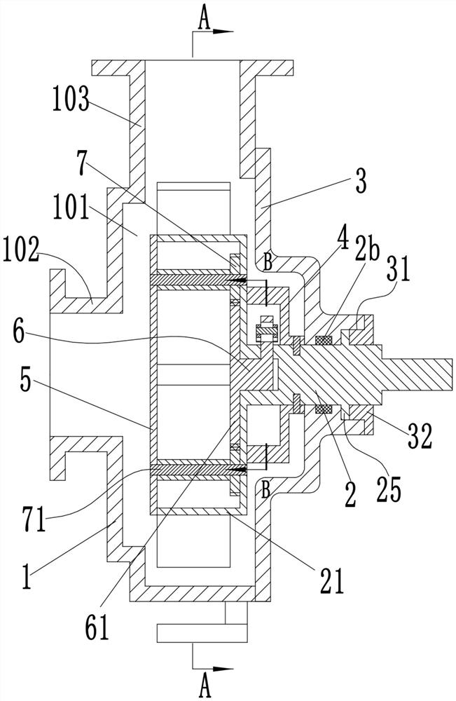
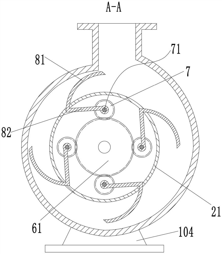
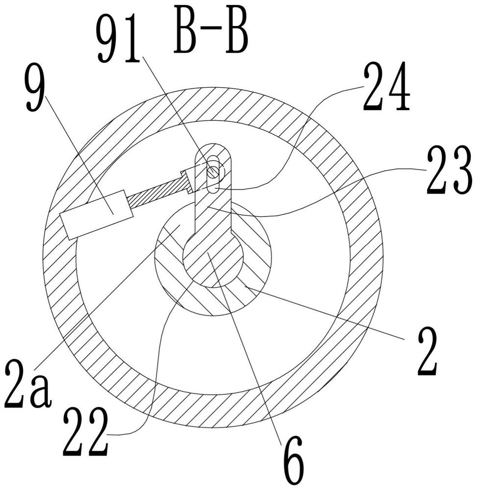
[0019] see Figure 1-5 As shown, a centrifugal water pump includes a pump body 1, a pump chamber 101 is arranged inside the pump body 1, and a pump cover 3 is fixedly installed at the opening of the right end of the pump chamber 101, and the pump cover 3 is rotatably connected to There is a power shaft 2 whose left end extends into the pump cavity 101, the side of the pump body 1 is provided with a water inlet pipe 102 along the axial direction of the power shaft 2, and a water outlet pipe 103 is provided along a direction perpendicular to the power shaft 2; The left end of the power shaft 2 is provided with a wheel housing 21 with a left end opening, and the left end of the power shaft 2 in the wheel housing 21 is provided with a shaft hole 22, and the shaft hole 22 is rotationally connected with a shaft rod 6, and the shaft rod 6 The left end is provided with a gear plate 61 located in the wheel housing 21; the opening of the left end of the wheel housing 21 is fixedly equip...


PUM


Abstract

The invention discloses a centrifugal water pump comprising a pump body. A pump cavity is arranged in the pump body. The opening of the right end of the pump cavity is fixedly provided with a pump cover. A power shaft with the left end extending into the pump cavity is rotationally connected into the pump cover. The side face of the pump body is provided with a water inlet pipe and a water outletpipeline. The left end of the power shaft is provided with a wheel shell. The portion, at the left end of the power shaft, in the wheel shell is provided with a shaft hole. A shaft rod is rotationallyconnected into the shaft hole. The left end of the shaft rod is provided with a toothed disk located in the wheel shell. The opening of the left end of the wheel shell is fixedly provided with a cover plate. Multiple rotating shafts are rotationally connected between the cover plate and the right end of the wheel shell. Each rotating shaft is fixedly provided with a gear. Each rotating shaft is fixedly provided with a connecting plate. Each connecting plate is provided with an arc blade. The side face of the wheel shell is provided with sliding grooves allowing the arc blades to extend therein. An adjusting assembly used for driving the shaft rod to rotate is arranged in the pump cavity. The centrifugal water pump is simple in structure, and the displacement can be adjusted.

Description

technical field [0001] The invention belongs to the technical field of centrifugal pumps, in particular to a variable displacement centrifugal water pump. Background technique [0002] A centrifugal pump is a machine that transports or pressurizes a liquid. It transmits the mechanical energy of the prime mover or other external energy to the liquid to increase the energy of the liquid. It is mainly used to transport liquids including water, oil, acid and alkali, emulsion, suspension, etc. Emulsions and liquid metals, etc., can also transport liquids, gas mixtures, and liquids containing suspended solids; the technical parameters to measure the performance of centrifugal pumps include flow rate, suction lift, head, shaft power, water power, efficiency, etc. Existing centrifugal pumps can only change the displacement of the pump by adjusting the rotational speed, which not only affects the efficiency and head of the pump, but also requires a speed regulating mechanism to contr...

Claims


Application Information

Patent Timeline
Patent Type & Authority Applications(China)
IPC IPC(8): F04D29/24F04D15/00
CPCF04D15/0055F04D29/242F04D29/247
Inventor 陈少同姜桂梅马玉英
Owner SHANGHAI LIANCHENG GRP SUZHOU
Why Eureka
Try Eureka