Double-fan-blade humidifying heater

A dual-blade and heater technology, applied in air humidification systems, heating methods, central heating components, etc., can solve problems such as air drying

Pending Publication Date: 2020-10-23
SHENZHEN LIANCHUANG TECHNOLOGY GROUP CO LTD
View PDF2 Cites 0 Cited by
  • Summary
  • Abstract
  • Description
  • Claims
  • Application Information

AI Technical Summary

Problems solved by technology

[0006] The purpose of the present invention is to provide a double-vane humidification heater, which can not only solve the problem of air drying in the heating p

Method used


Image

  • Double-fan-blade humidifying heater
  • Double-fan-blade humidifying heater
  • Double-fan-blade humidifying heater

Examples


Embodiment 1

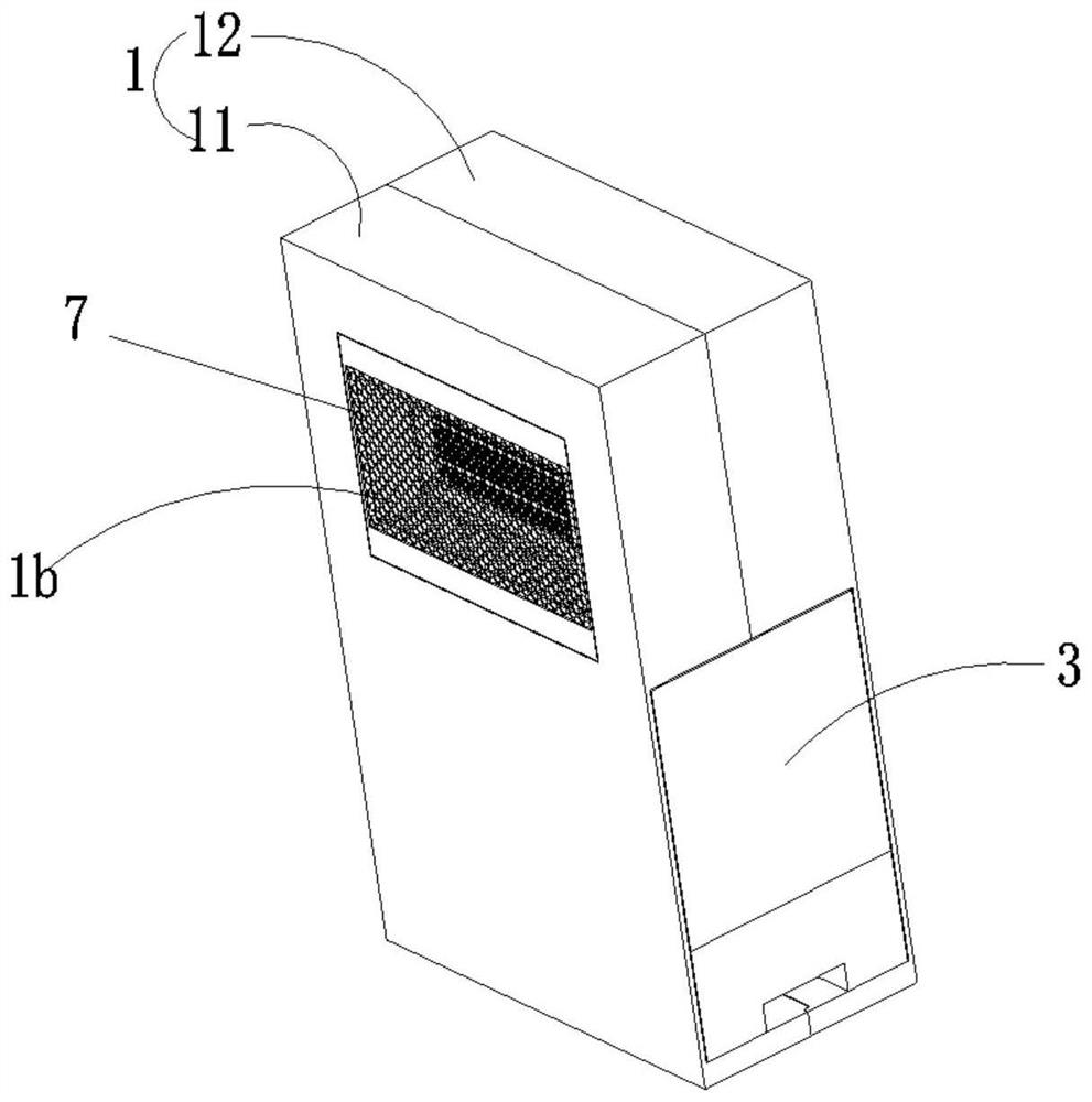
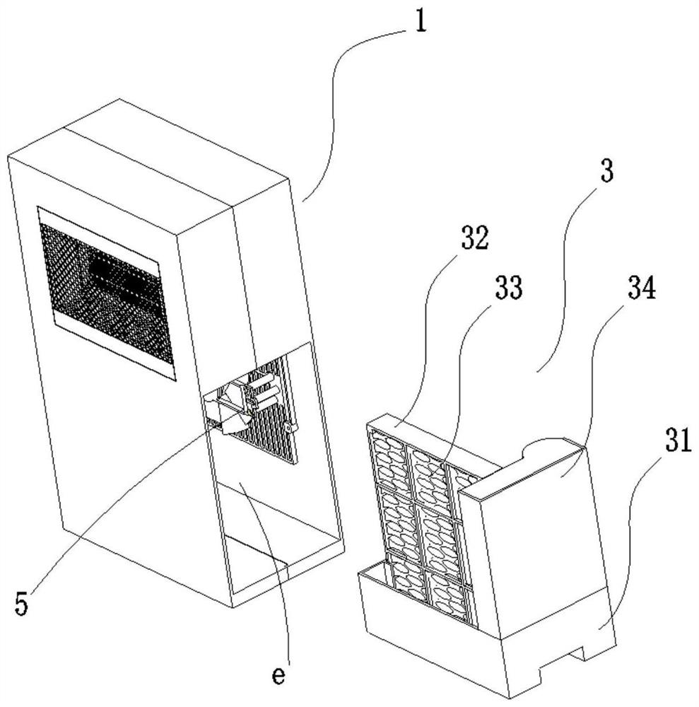
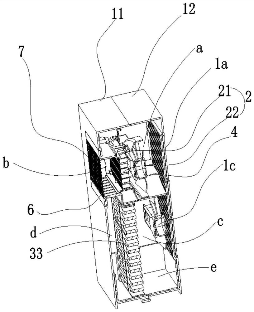
[0042] Such as figure 1 , figure 2 , image 3 and Figure 4 As shown, the present invention provides a double-blade humidification heater, including a casing 1, a heating assembly 2 and a humidifying assembly 3 located in the casing 1, and the heating assembly 2 and the humidifying assembly 3 are independently arranged in the casing 1 The warm air inlet channel a and the warm air outlet channel b are formed between the heating component 2 and the housing 1, and the warm air inlet channel b corresponding to the warm air inlet channel a and the warm air outlet channel b is provided on the housing 1 The air outlet 1a and the warm air outlet 1b, the heating fan 4 is arranged in the warm air inlet channel a; the humidification air inlet channel c and the humidification air outlet channel d are formed between the humidification component 3 and the casing 1, and the casing 1 is provided with The humidification air inlet 1c corresponding to the humidification air inlet channel c i...

Embodiment 2

[0051] Such as Figure 5 and Figure 6 As shown, different from Embodiment 1, the present invention also has a humidification air outlet 1d connected to the humidification air outlet channel d on the casing 1, and the humidification air outlet 1d is located below the warm air outlet 1b, wherein The humidification air outlet channel d is directly connected to the humidification air outlet 1d, that is, the heating and humidification channels are separated.

[0052] Such as Figure 5 As shown, the fan grille is installed at the humidification air outlet 1d, and the blowing direction can be adjusted by adjusting the angle of the fan grille. The humidifying fan 5 sucks in the external air from the humidifying air inlet 1c and enters the humidifying air inlet channel c, is humidified by the humidifying component 3 and then discharged from the humidifying air outlet 1d after passing through the humidifying air outlet channel d.

[0053] When heating is used, driven by the heating ...


PUM


Abstract

The invention discloses a double-fan-blade humidifying heater. The double-fan-blade humidifying heater comprises a shell, a heating assembly and a humidifying assembly, wherein the heating assembly and the humidifying assembly are arranged in the shell independently; a warm air inlet channel (a) and a warm air outlet channel (b) are formed between the heating assembly and the shell; a warm air inlet corresponding to the warm air inlet channel is formed in the shell; a warm air heater is arranged in the warm air inlet channel (a); a humidifying air inlet channel is formed between the humidifying assembly and the shell; a humidifying air inlet (1c) corresponding to the humidifying air inlet channel (c) is formed in the shell; a humidifying fan (5) is arranged in the humidifying air inlet channel (c); and a humidifying air outlet channel (d) communicates with the warm air outlet channel (b). The double-fan-blade humidifying heater not only can solve the problem of air drying in the heating process, but also has high enough safety coefficients, so that neither danger of hurting people by high-temperature water vapor nor hidden danger of electric safety exists.

Description

technical field [0001] The invention relates to the technical field of air conditioning, in particular to a humidifying heater with double fan blades. Background technique [0002] In the cold winter, especially in areas without heating, many people will choose to use electric heaters to heat indoors, but the use of heaters will inevitably cause the indoor humidity to decrease and the air to dry out. Long-term use in such an environment will cause Human body discomfort; especially the heater, because it has a fan to force the hot air convection, which will aggravate the indoor drying; [0003] Now there are some natural convection heaters in the world that add an open water box outside the body, using the temperature generated by the heater to evaporate the water to humidify the room, but the evaporation of water in this way is small, and the humidification effect is not ideal; [0004] Chinese patent document CN 107621060 A adopts the method of adding heating tubes in the ...

Claims


Application Information

Patent Timeline
IPC IPC(8): F24D13/02F24D19/00F24F6/04
CPCF24D13/02F24D19/0082F24D2200/08F24D2220/2036F24F6/04
Inventor 赖伴来庞亚鹏
Owner SHENZHEN LIANCHUANG TECHNOLOGY GROUP CO LTD
Why Eureka
Try Eureka