Servo motor shaft assembling equipment and method

A servo motor and shaft assembly technology, which is applied in the manufacture of stator/rotor bodies, centering/balancing rotors, etc., can solve problems such as shell damage, shaft misalignment through holes, etc.

Inactive Publication Date: 2020-10-23
王加县
View PDF0 Cites 1 Cited by
  • Summary
  • Abstract
  • Description
  • Claims
  • Application Information

AI Technical Summary

Problems solved by technology

[0003] In order to solve the problem of assembling the above-mentioned traditional process, only the cylindrical outer surface of the shell is positioned, and the through hole on the shell is not positioned. Since the shell is small in size and the through hole in the center of the shell is also small, in When assembling with the s

Method used


Image

  • Servo motor shaft assembling equipment and method
  • Servo motor shaft assembling equipment and method
  • Servo motor shaft assembling equipment and method

Examples


Embodiment Construction

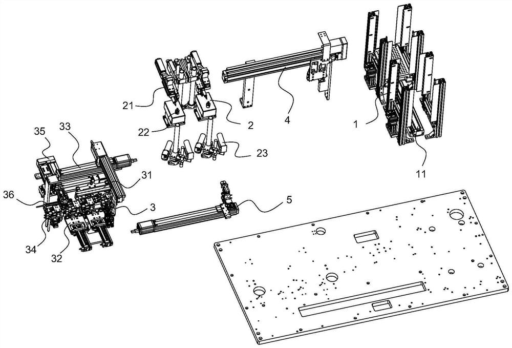
[0023] Such as figure 1 The shown servo motor shaft assembly equipment includes a bottom plate and a shaft feeding device 1 , a lubricating device 2 , a shaft insertion device 3 , a first conveying device 4 and a second conveying device 5 installed on the bottom plate. The shaft feeding device 1, the lubricating device 2 and the shaft inserting device 3 are fixed on the bottom plate in sequence, the shaft feeding device 1 and the lubricating device 2 are connected by the first conveying device 4, and the lubricating device 2 and the shaft inserting device 3 are passed through The second transport device 5 is connected. The shaft is placed on the pallet and enters the shaft feeding device 1. The shaft feeding device 1 is used for conveying the pallet. The first transport device 4 transfers the shaft on the pallet to the lubricating device 2. The lubricating device 2 is used to wipe the surface of the shaft. oil, the second conveying device 5 is used to carry the oiled shaft in...


PUM


Abstract

The invention relates to the field of motor assembly, in particular to servo motor shaft assembly equipment, which comprises a bottom plate, a shaft feeding device, a lubricating device, a shaft inserting device, a first carrying device and a second carrying device which are mounted on the bottom plate, wherein the shaft inserting device comprises a shaft arranging mechanism, an outer shell feeding mechanism, a carrying mechanism, a double-station assembling mechanism and a shaft pressing mechanism; the double-station assembling mechanism comprises an assembling frame and a first assembling assembly; a left positioning hole and a right positioning hole are formed in a jig, and the first positioning rod is located under the left positioning hole; and the second positioning rod is located under the right positioning hole. According to the servo motor shaft assembling equipment and the method, the through hole in the shell is preferentially positioned, the outer shell is immediately fixedafter positioning is completed, thereby guaranteeing that the shaft can be inserted into the through hole.

Description

technical field [0001] The invention relates to the field of motor assembly, in particular to a servo motor shaft assembly device and a method thereof. Background technique [0002] Both the shaft and the shell are cylindrical, and the shell is provided with a through hole. When the shaft is assembled, first grease the shaft and then insert it into the shell. When assembling in the traditional process, only the cylindrical outer surface of the shell is positioned, and the through hole on the shell is not positioned. Since the shell is small in size and the through hole in the center of the shell is also small, it is difficult to assemble with the shaft. When the shaft is misaligned, it is easy to appear through holes, which not only affects the efficiency of shaft assembly, but also causes damage to the housing if it cannot be inserted into the housing. Contents of the invention [0003] In order to solve the problem of assembling the above-mentioned traditional process, ...

Claims


Application Information

Patent Timeline
IPC IPC(8): H02K15/02H02K15/16
CPCH02K15/02H02K15/16
Inventor 王加县曹春云曹二菊
Owner 王加县
Why Eureka
Try Eureka