
Flexible concave grid with rotatable threshing units

A concave plate sieve, flexible technology, applied in threshing equipment, agricultural machinery and tools, agriculture, etc., can solve problems such as grain damage and poor separation effect

Active Publication Date: 2020-10-27
HENAN UNIV OF SCI & TECH
View PDF22 Cites 0 Cited by
  • Summary
  • Abstract
  • Description
  • Claims
  • Application Information

AI Technical Summary

Problems solved by technology

[0004] The purpose of the present invention is to provide a flexible concave screen with a rotatable threshing unit to solve the problem that the existing concave screen easily causes damage to the grain and poor separation effect during the collision process with the threshing drum and the grain

Method used


Image

  • Flexible concave grid with rotatable threshing units
  • Flexible concave grid with rotatable threshing units
  • Flexible concave grid with rotatable threshing units

Examples


Embodiment 1

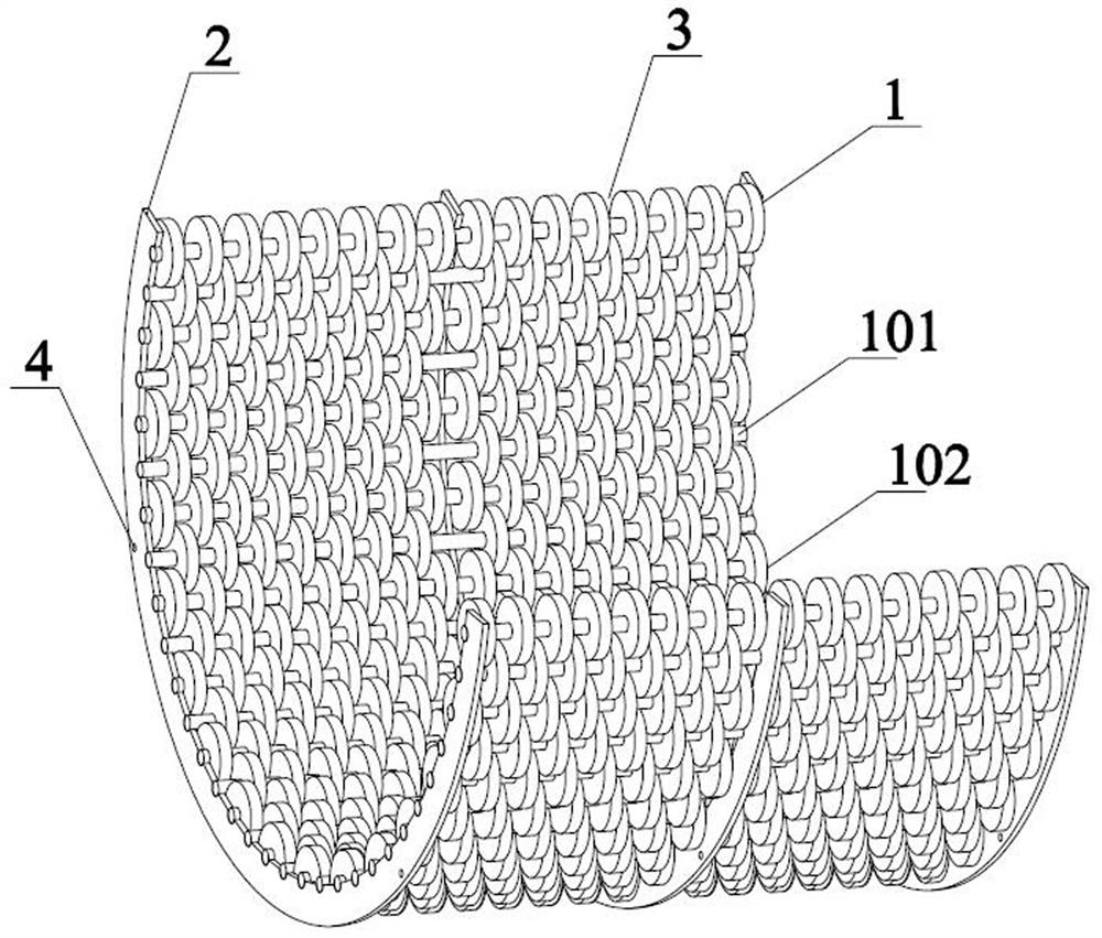
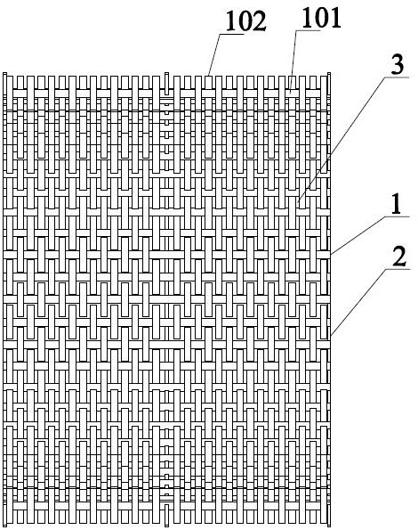
[0024] like figure 2 As shown, in this embodiment, the distance between the connecting shafts 101 in any two adjacent flexible threshing unit groups 1 is the same as the difference between the outer diameter and the inner diameter of the threshing unit 102, and the height of the threshing unit is smaller than that of any two adjacent flexible threshing units. The distance between adjacent threshing units on the same connecting shaft 101, between any threshing unit and the threshing units in the previous flexible threshing unit group 1 and between the threshing units in the next flexible threshing unit group 1 Both form threshing holes 3 for grain separation.

Embodiment 2

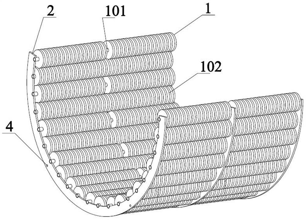
[0026] like Figure 4 As shown, in this embodiment, the height of the threshing unit is equal to the distance between any two adjacent threshing units located on the same connecting shaft 101, and the distance between the connecting shafts 101 in any two adjacent flexible threshing unit groups 1 The distance between them is greater than the difference between the outer diameter and the inner diameter of the threshing unit; between two adjacent threshing units located on the same connecting shaft 101, between the threshing unit and the threshing unit in the previous flexible threshing unit group 1, and between the threshing units Threshing holes 3 for grain separation are formed between the unit and the threshing units in the next flexible threshing unit group 1 .

[0027] When the present invention cooperates with the threshing drum for threshing, at the moment of contact between the two, since the material of the threshing unit is hollow wear-resistant rubber, the rigid impac...


PUM


Abstract

The invention provides a flexible concave grid with rotatable threshing units. The flexible concave grid comprises a plurality of flexible threshing unit groups, wherein each flexible threshing unit group comprises a connecting shaft and threshing units which are rotatably arranged on the connecting shaft at intervals, the connecting shaft is fixedly arranged on a plurality of side arc plates which are arranged in parallel, and the threshing units on any two groups of adjacent flexible threshing units are arranged in a staggered mode. When the flexible concave grid provided by the invention ismatched with a threshing cylinder for threshing, when the threshing units make contact with the threshing cylinder, rigid impact is changed into flexible impact due to the fact that the threshing units are made of hollow wear-resisting rubber, and the impact force generated during contact can be greatly reduced; and meanwhile, the hollow wear-resisting rubber threshing units can rotate around theconnecting shaft in a threshing process, rolling threshing is achieved in the threshing process, the husks of unhusked rice can be separated from grains through shearing force generated by rolling force, and thus a threshing rate can be increased.

Description

technical field [0001] The invention belongs to the field of agricultural machinery equipment, in particular to a flexible concave screen with a rotatable threshing unit. Background technique [0002] The traditional way of harvesting millet is mainly to harvest millet manually, and then grind the millet with stones, which not only has high labor intensity but also very low production efficiency, making it difficult to make ends meet. Today, with the continuous improvement of agricultural mechanized production, such traditional harvesting The way is that it cannot meet the requirements of the society, so the production of millet in our country is far from enough, and it also greatly limits the development of millet and its related industries in our country. [0003] At present, millet threshing is mainly in the form of full feeding and is improved on the basis of the previously developed wheat and rice threshing drum. The modified threshing separation effect is not good. Gen...

Claims


Application Information

Patent Timeline
Patent Type & Authority Applications(China)
IPC IPC(8): A01F7/02A01F12/24
CPCA01F7/02A01F12/24Y02P60/14
Inventor 李心平王文哲卢文涛耿令新姬江涛
Owner HENAN UNIV OF SCI & TECH
Learn More