Fire source space positioning method and system based on two fire monitors

A technology of spatial positioning and fire monitors, which is applied in fire rescue and other fields, can solve the problems of large amount of data calculation, difficult data processing, and high reconstruction cost

Inactive Publication Date: 2020-10-27
HEFEI KDLIAN SAFETY TECHNOLOGY CO LTD
View PDF7 Cites 0 Cited by
  • Summary
  • Abstract
  • Description
  • Claims
  • Application Information

AI Technical Summary

Problems solved by technology

That is to say, a method for spatially locating the same fire source through multiple positioning modules is disclosed, but the main body used is on the fire-fighting robot, and a corresponding number of positioning modules such as infrared cameras can be set as required during the production and assembly of the robot. For the fire monitors of the common fixed fire protection system, each fire monitor is equipped with only one positioning module, and the binocular positioning method needs to upgrade the entire fire protection system; due to the different fixed positions of the fire monitors, the fire monitor and the positioning module The relative height of each fire monitor is different, and the control parameters need to be configured separately for each fire monitor, and when using the infrared camera to determine the distance and azimuth of the fire source, it is necessary to use the parameters obtained by the camera itself to participate in the calculation, and the amount of data calculation is large, so this method When applied to existing fire monitors, there are problems such as high modification cost and difficult data processing

Method used


Image

  • Fire source space positioning method and system based on two fire monitors
  • Fire source space positioning method and system based on two fire monitors
  • Fire source space positioning method and system based on two fire monitors

Examples


Embodiment Construction

[0042] In order to make the object, technical solution and advantages of the present invention clearer, the present invention will be further described in detail below in conjunction with specific embodiments and with reference to the accompanying drawings.

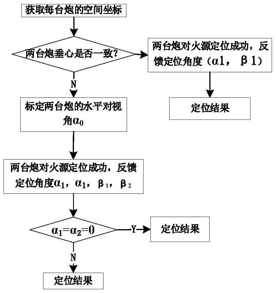
[0043] Such as figure 1 As shown, the present embodiment provides a fire source spatial positioning method based on two fire monitors, comprising the following steps:

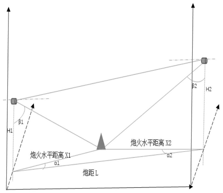
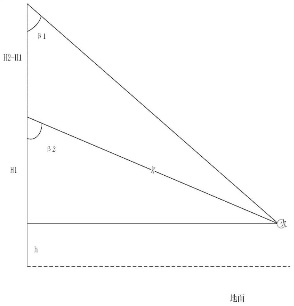
[0044] Step A: Construct a three-dimensional coordinate system in space, take the ground as the XOY plane, and vertically upward as the positive direction of the Z-axis, figure 2 In the middle, the horizontal direction to the right is the X-axis square, and the vertical XOZ plane is the positive direction of the Y-axis; two fire monitors are selected from the fire monitors that detect the fire, and their heights H are obtained respectively. 1 and H2 , the distance L between the orthocenters, and the positioning pitch angle β to the fire source position ...


PUM


Abstract

The invention provides a fire source space positioning method based on two fire monitors. The method comprises the following steps: A, a space three-dimensional coordinate system is constructed, the two fire monitors are selected, and a height H1 and a height H2, a distance L between the vertical centers of the height H1 and the height H2 and a positioning pitch angle beta 1 and a positioning pitch angle beta 2 of the position of a fire source are correspondingly obtained; B, if L is not equal to 0, a horizontal offset angle alpha 1 and a horizontal offset angle alpha 2 of the two fire monitors are calibrated, and otherwise, the step B is skipped; and C, the height of the fire source position under the three-dimensional coordinate system is calculated, and the spatial position of the firesource is determined. The invention also provides a positioning system based on the positioning method. The method has the advantages that the position of the fire source is determined only by relyingon the angle information of the two fire monitors and the positions of the fire monitors, an original fire monitor does not need to be modified, the distance of the fire source is determined by parameters of the camera, the erection cost is lower, the calculation method is simple, and the response speed is improved.

Description

technical field [0001] The invention relates to the technical field of fire fighting, in particular to a fire source spatial positioning method and system based on two fire monitors. Background technique [0002] Fire source positioning is the key element for accurate fire extinguishing of fire-fighting products. When a single fire monitor locates the fire source, it scans the fire source by rotating the camera fixed on the top of the intelligent fire monitor barrel. When the flame is located at the center of the imaging, it realizes position. However, due to the lack of information on the height of the fire source, the accuracy of fire extinguishing is not accurate in practical applications. At present, the commonly used spatial positioning method is obtained by using complex coordinate system conversion formulas, and the calculation accuracy is greatly affected by the internal and external parameters of the camera. Therefore, there is an urgent need for a more efficient ...

Claims


Application Information

Patent Timeline
Patent Type & Authority Applications(China)
IPC IPC(8): A62C37/00A62C31/00
CPCA62C31/00A62C37/00
Inventor 石晓龙徐云绯许玉坤金卫东周扬巢佰崇张克年杨广
Owner HEFEI KDLIAN SAFETY TECHNOLOGY CO LTD
Why Eureka
Try Eureka