A water separator and a fuel cell

A fuel cell and water separator technology, applied in the directions of fuel cells, chemical instruments and methods, circuits, etc., can solve the problems of unfavorable water separation device layout integration applicability and system volume power density, fixed water separator size, affecting fuel cells. performance and other issues, to achieve the effect of avoiding the performance degradation of the stack, high layout integration adaptability, and good water separation efficiency

Active Publication Date: 2022-05-03
SHANGHAI HYDROGEN PROPULSION TECH CO LTD
View PDF14 Cites 0 Cited by
  • Summary
  • Abstract
  • Description
  • Claims
  • Application Information

AI Technical Summary

Problems solved by technology

[0005] For the first type of device, considering the water separation efficiency, the gas-liquid mixture needs to form a sufficiently large vortex and centrifugal force, so the size of the water separator is relatively fixed and the volume is large, which is not conducive to improving the layout and integration applicability of the water separation device and the system Volume power density
For the second type of device, the flow resistance is too large, which leads to an increase in the performance requirements of the circulation device; under the action of long-term gas flushing, the internal material may fall off, block the flow channel, and seriously affect the performance of the fuel cell

Method used


Image

  • A water separator and a fuel cell
  • A water separator and a fuel cell
  • A water separator and a fuel cell

Examples


no. 1 Embodiment

[0056] The first specific embodiment of the present invention provides a water separator.

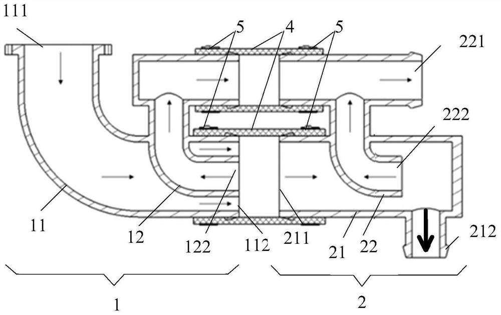
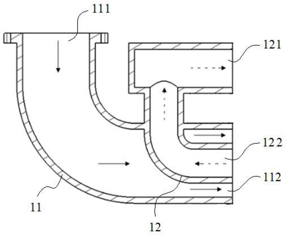
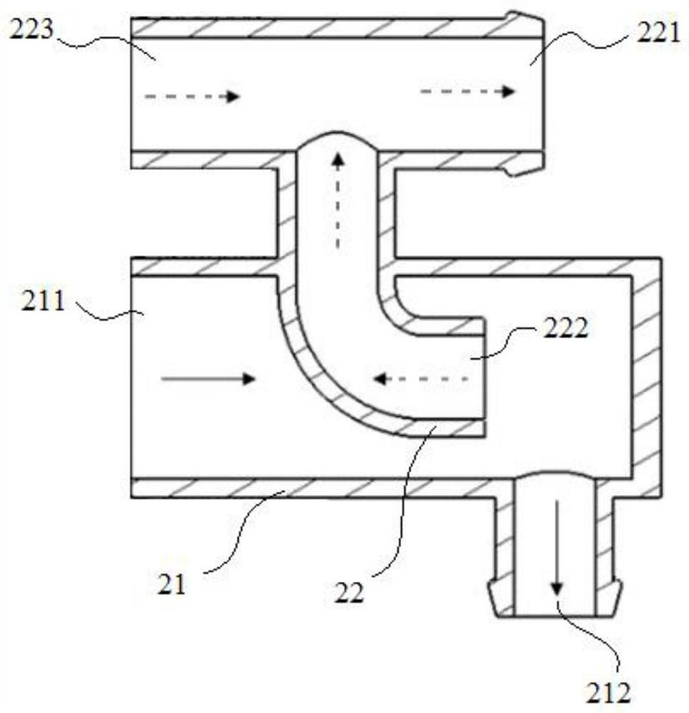
[0057] see Figure 1 to Figure 3 , figure 1 A cross-sectional view of the water separator provided for the first specific embodiment of the present invention; figure 2 A sectional view of the first water diversion section provided for the first specific embodiment of the present invention; image 3A cross-sectional view of the water diversion section at the tail provided for the first specific embodiment of the present invention.

[0058] The water separator provided by the first specific embodiment of the present invention includes a first water diversion section 1 and a tail water diversion section 2, wherein:

[0059] a) The head water diversion section 1 includes the head main flow pipe 11 and the head drainage pipe 12 . Both ends of the head main flow pipe 11 are respectively provided with a mixed fluid inlet 111 and a head fluid outlet 112 . The first drainage pipe 12 includ...

no. 2 Embodiment

[0079] The second specific embodiment of the present invention provides a water separator.

[0080] see Figure 4 to Figure 6 , Figure 4 A cross-sectional view of the water separator provided for the second specific embodiment of the present invention; Figure 5 A cross-sectional view of the middle water-cutting section provided for the second specific embodiment of the present invention; Figure 6 It is a schematic diagram of the overall structure of the water separator provided in the second specific embodiment of the present invention.

[0081] The only difference between the water separator provided by the second specific embodiment of the present invention and the water separator provided by the first specific embodiment of the present invention is that the water separator provided by the second specific embodiment of the present invention is different from that provided by the first specific embodiment. On the basis of the water separator, an intermediate water diver...

no. 3 Embodiment

[0088] The third specific embodiment of the present invention provides a water separator.

[0089] The difference between the water separator provided by the third specific embodiment of the present invention and the water separator provided by the second specific embodiment of the present invention is only that: a plurality of intermediate water diversion sections are arranged in series in sequence, and the middle of the multiple intermediate water diversion sections The main flow pipes are connected at the ends in sequence, and the connecting pipe sections in the multiple intermediate water diversion sections are connected at the ends in sequence. For details, see Figure 4 , the water separator provided by the third specific embodiment of the present invention, in Figure 4On the basis of this, multiple intermediate water diversion sections 3 are arranged in parallel.

[0090] Wherein, in the middle water diversion section 3 at the head end, the middle fluid inlet 311 of ...


PUM


Abstract

The invention discloses a water divider and a fuel cell. The water divider includes a first partial water section and a tail partial water section, wherein: the first partial water section includes a main main pipe at the head and a drainage pipe at the head, and the drainage pipe at the first section can The gas separated in the main main pipe at the first part is reversely drained and exported; the tail water section includes the main main pipe at the tail and the drainage pipe at the rear, and the drainage pipe at the rear can carry out reverse drainage and output the gas separated in the main main pipe at the rear. The water separator uses inertial force to separate the liquid droplets in the gas-liquid mixture from the gas, which can ensure good water separation efficiency and solve the technical problems of large device volume and large flow resistance in the prior art. Furthermore, the water separator can also be configured as a multi-level flexible structure to improve the applicability of the water separator.

Description

technical field [0001] The invention relates to the technical field of fuel cells, in particular to a water separator and a fuel cell provided with the water separator. Background technique [0002] The existing water separators for fuel cells can be divided into two categories based on basic principles: [0003] (1) Centrifugal force is used to separate liquid droplets, and guide vanes, or baffle structures, or spiral flow channels are used in the water separator to induce the gas-liquid mixture to rotate at high speed, and the liquid droplets are thrown to the water separator under the action of centrifugal force The inner wall of the device and flow down to achieve the purpose of separation from the gas; [0004] (2) Utilize the droplet adhesion, adopt filter element or corrugated plate and other structures to increase the contact area between the droplet and the surrounding wall surface, so that the droplet adheres to the wall surface and achieves the purpose of separat...

Claims


Application Information

Patent Timeline
Patent Type & Authority Patents(China)
IPC IPC(8): B01D45/04H01M8/0662H01M8/04119H01M8/04089
CPCB01D45/04H01M8/0662H01M8/04097H01M8/04164Y02E60/50
Inventor 尚鹏飞李秋红贾勇琪侯中军蔡俊王克勇
Owner SHANGHAI HYDROGEN PROPULSION TECH CO LTD
Why Eureka
Try Eureka