
Boosting joint, boosting supporting leg and boosting exoskeleton

A technology for supporting legs and joints, applied in the field of exoskeleton, which can solve the problems that the power assist system cannot predict the walking direction of the human body, walking failure, etc.

Active Publication Date: 2020-10-27
重庆悦强电子有限公司
View PDF12 Cites 3 Cited by
  • Summary
  • Abstract
  • Description
  • Claims
  • Application Information

AI Technical Summary

Problems solved by technology

Existing power-assisted exoskeletons generally have a complex power-assisted system, and the power-assisted system first needs to collect data to predict the walking movement of the human body in order to provide assistance, and when the first step of walking is started, the power-assisted system cannot predict the walking direction and movement of the human body At this time, it is generally necessary for the human body to overcome the resistance of the power assist system to perform walking movements before providing power assistance. This is a great burden for the elderly who have difficulty walking or people who are tired from walking for a long time, and even lead to walking failure because they cannot take the first step The problem

Method used


Image

  • Boosting joint, boosting supporting leg and boosting exoskeleton
  • Boosting joint, boosting supporting leg and boosting exoskeleton
  • Boosting joint, boosting supporting leg and boosting exoskeleton

Examples


Embodiment Construction

[0041] The present invention will be further described below in conjunction with the accompanying drawings and specific embodiments, so that those skilled in the art can better understand the present invention and implement it, but the examples given are not intended to limit the present invention.

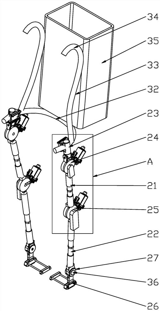
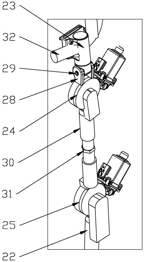
[0042] Such as figure 1 Shown is a schematic structural diagram of an embodiment of the power-assisted exoskeleton of the present invention. The power-assisted exoskeleton of this embodiment includes a waist link 32 , and power-assisted supporting legs are respectively provided under both ends of the waist link 32 . Specifically, the booster supporting leg of this embodiment includes a thigh link 21 and a calf link 22 . A hip joint 23 is arranged above the thigh connecting rod 21, and a hip joint 24 is arranged between the hip connecting member 23 and the thigh connecting rod; a knee joint 25 is arranged between the thigh connecting rod 21 and the calf connecting rod 22; A foot ...


PUM


Abstract

The invention discloses a boosting joint comprising a joint seat. The joint seat is provided with a rotating shaft which is in rotating fit with the joint seat and a boosting drive mechanism used fordriving the rotating shaft to rotate relative to the joint seat. The boosting drive mechanism comprises a drive wheel arranged outside the rotating shaft in a sleeving manner and a power mechanism used for driving the drive wheel to rotate. A rotation limiting structure used for limiting the angle range in which the rotating shaft can freely rotate relative to the drive wheel is arranged between the rotating shaft and the drive wheel. The invention also provides a boosting supporting leg and a boosting exoskeleton. By arranging the rotation limiting structure between the rotating shaft and thedriving wheel, the rotating shaft can rotate freely within the angle range limited by the rotation limiting structure, and then a margin of rotation is reserved between the rotating shaft and the driving wheel; in this way, the user can use the leg to drive the rotating shaft to rotate freely relative to the driving wheel at the starting stage, so that the walking data of the user can be obtained, the walking intention of the user can be predicted; and then it is convenient to use the boosting drive mechanism to provide boosting.

Description

technical field [0001] The invention relates to an exoskeleton, in particular to a power-assisted joint, a supporting leg and an exoskeleton. Background technique [0002] In some scenarios where traditional wheeled vehicles are difficult to apply, human or animal power is often required to carry objects. For example, when porters carry goods up and down stairs, when scientific research and firefighters work in the field, and when soldiers walk with heavy loads in mountainous areas, they all need to carry heavy loads for long-distance walking. Excessive loads will cause certain damage to the human body. In addition, as the global aging problem becomes more and more serious, exoskeletons can help some elderly people to solve the problem of poor physical strength and unchanged walking, and help some people who have lost their mobility to recover part of their mobility. [0003] The characteristic of the power-assisted exoskeleton is that it requires collaboration with the wea...

Claims


Application Information

Patent Timeline
Patent Type & Authority Applications(China)
IPC IPC(8): B25J17/00B25J17/02B25J9/00B25J19/02
CPCB25J17/00B25J17/02B25J9/00B25J19/02B25J9/0006
Inventor 李文军
Owner 重庆悦强电子有限公司
Learn More