Cement adding and automatic bag opening equipment for concrete stirring
A concrete and cement technology, applied in the direction of selling raw material supply devices, etc., can solve the problems of complex structure, physical damage to workers, and high cost
- Summary
- Abstract
- Description
- Claims
- Application Information
AI Technical Summary
Problems solved by technology
Method used
Image
Examples
Embodiment 1
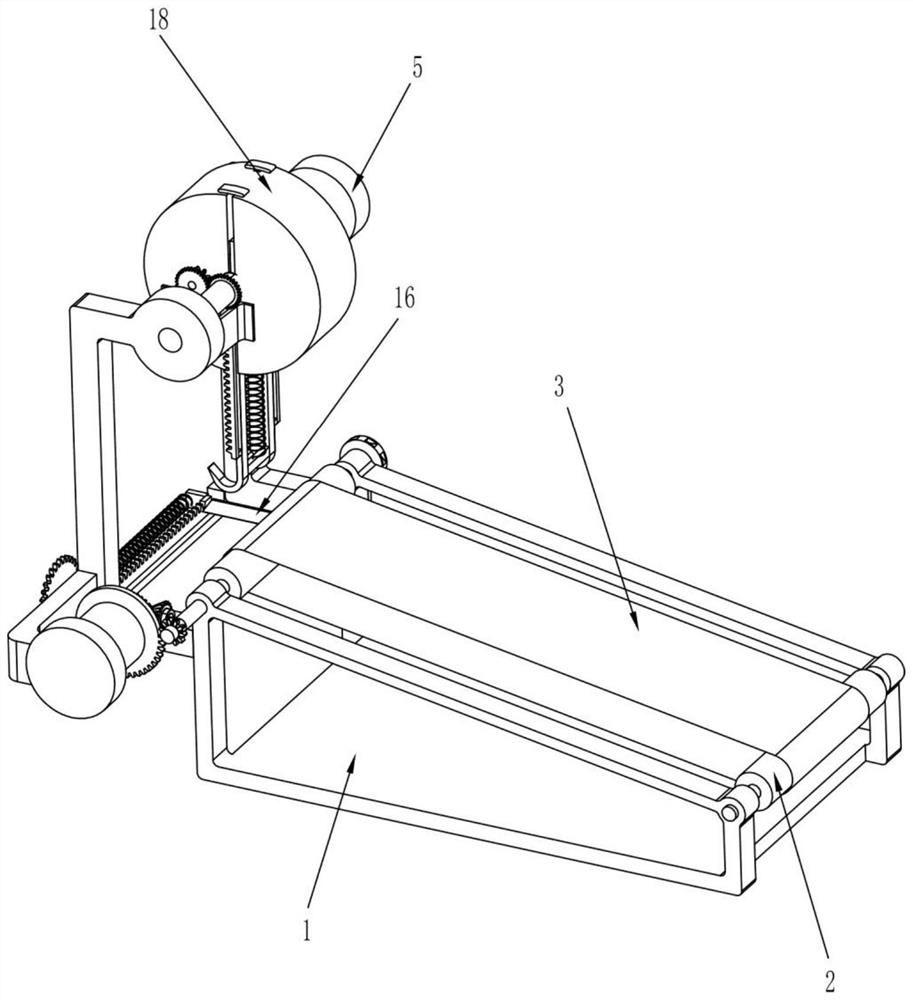
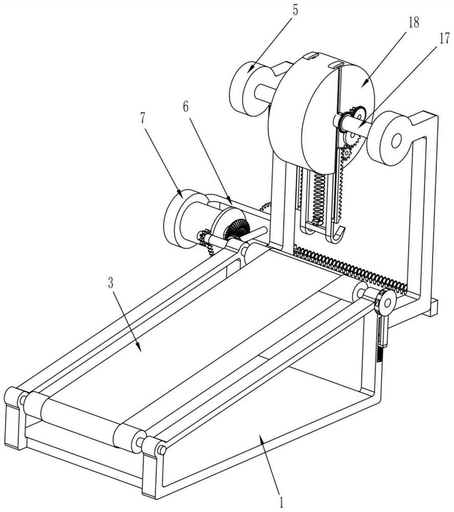
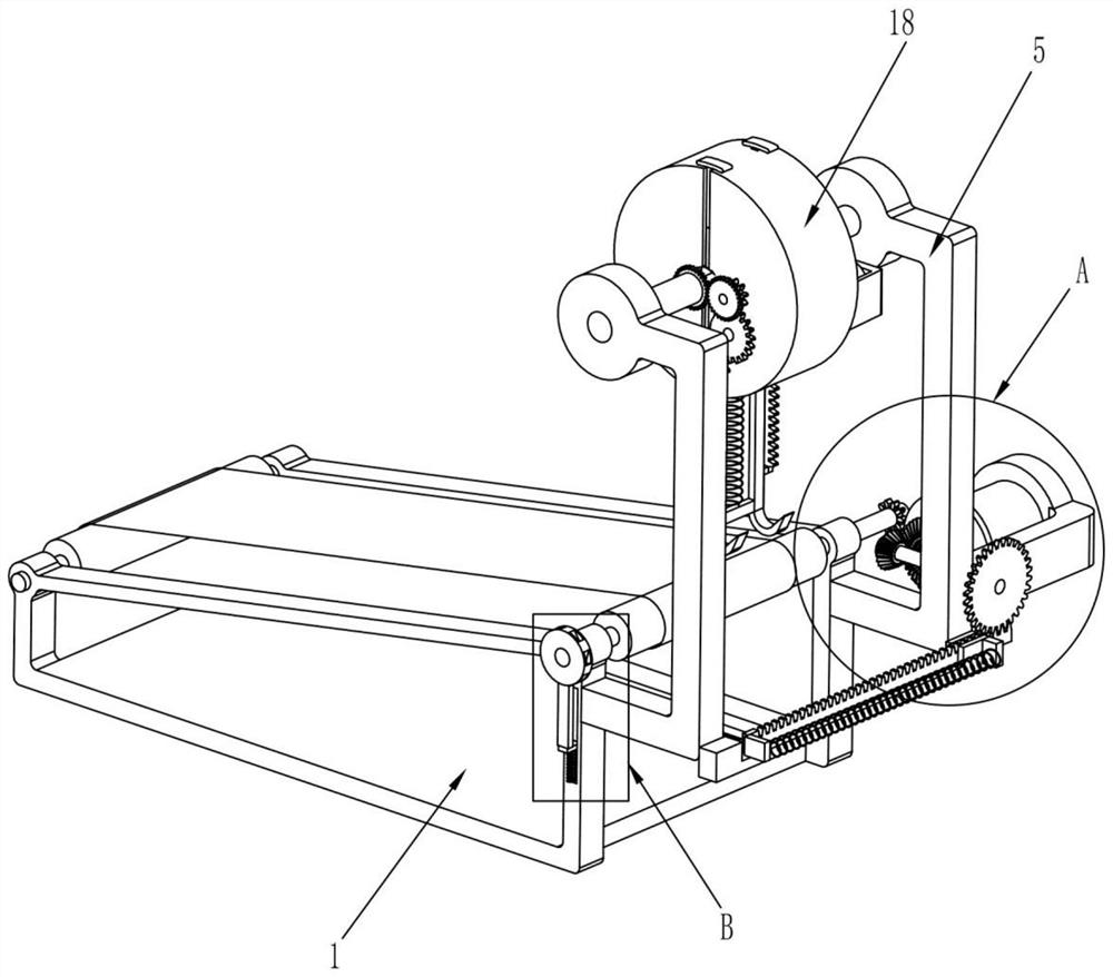
[0025] A kind of cement adding automatic bag opening equipment for concrete mixing, such as Figure 1-10 As shown, it includes a mounting frame 1, a transmission wheel 2, a conveyor belt 3, a pinion 4, a mounting plate 5, a fixing plate 6, a driving motor 7, a power sector gear 8, a tooth-less bevel gear 9, a rotating shaft 10, and a small bevel gear 11. Transmission gear 12, bag opening mechanism, fixed shaft 17, fixed gear 171, rotating disc 18 and rotating mechanism, a chute is provided on the mounting frame 1, and a transmission conveyor is installed at both ends of the mounting frame 1 in a rotating manner. Wheel 2, a conveyor belt 3 for driving bagged cement is connected between the two transmission wheels 2, and the conveyor belt 3 is provided with corrugations, the pinion 4 is fixedly installed on one end of one of the transmission wheels 2, and the installation One side of the frame 1 is fixedly installed with two symmetrical mounting plates 5 and the mounting plate 5...
Embodiment 2
[0032] On the basis of Embodiment 1, such as Figure 9-10 As shown, it also includes an anti-backward mechanism 31 for preventing the bagged cement on the conveyor belt 3 from falling behind. The anti-backward mechanism 31 is installed on the mounting frame 1 and one of the transmission wheels 2. The anti-backward mechanism 31 includes Slider 311, extruding spring 312, draw bar 313 and chuck 314, on the described installation frame, offer a chute and slide block is slidably installed in the chute, the bottom side of described slider 311 and installation frame 1 An extruding spring 312 is installed between them, the clamping rod 313 is fixedly mounted on the upper side of the slider 311, the chuck 314 is fixedly mounted on one end of the transmission wheel 2 away from the pinion 4 and the chuck 314 is provided with Seven draw-in slots, the upper end of the draw-in rod 313 can be in contact with the draw-in slots on the chuck 314, and the cooperation between the draw-in bar 313 ...
PUM
 Abstract
Description
Claims
Application Information
 - R&D
- Intellectual Property
- Life Sciences
- Materials
- Tech Scout
- Unparalleled Data Quality
- Higher Quality Content
- 60% Fewer Hallucinations
Browse by: Latest US Patents, China's latest patents, Technical Efficacy Thesaurus, Application Domain, Technology Topic, Popular Technical Reports.
© 2025 PatSnap. All rights reserved.Legal|Privacy policy|Modern Slavery Act Transparency Statement|Sitemap|About US| Contact US: help@patsnap.com


