Method for positioning material sheet paved on slender soft mold

A positioning method and soft technology, applied in the field of sheet positioning, can solve the problems of time-consuming and labor-intensive pre-laid fibers, appearance deformation, and mechanical performance degradation of parts

Active Publication Date: 2020-10-27
航天海鹰(镇江)特种材料有限公司
View PDF6 Cites 1 Cited by
  • Summary
  • Abstract
  • Description
  • Claims
  • Application Information

AI Technical Summary

Problems solved by technology

Especially the fiber angle of ±45° unidirectional fiber prepreg paving, if there is a deviation, the appearance of the part will be deformed after curing, which will reduce the mechanical properties of the part
[0003] At present, the molding method based on the autoclave process in the industry is basically metal mandrel molding or soft mold molding. Metal material, heavy weight, very inconvenient to operate, and in the case of large composite material parts, in order to ensure product dimensional accuracy and positioning benchmarks, the precision requirements of the mold must be high
In the soft mold molding process, due to the poor strength and stability of the soft mold itself and the large deviation in positioning, it is impossible to directly lay and position on the soft mold. Generally, special metal tooling is used to lay the material. , and then manually transferred to the airbag tooling for combined positioning, which is time-consuming and labor-intensive, and there is a risk of buckling of the pre-laid fiber during the transfer process

Method used


Image

  • Method for positioning material sheet paved on slender soft mold
  • Method for positioning material sheet paved on slender soft mold
  • Method for positioning material sheet paved on slender soft mold

Examples


Embodiment Construction

[0031] The technical scheme of the present invention will be clearly and completely described below in conjunction with the embodiments and the accompanying drawings. Obviously, the described embodiments are only preferred embodiments of the present invention, not all embodiments, nor are they intended to be a reference to the present invention. For other forms of limitations, any skilled person who is familiar with this field may use the disclosed technical content to make changes or remodel equivalent changes. However, any simple modifications, equivalent changes and modifications made to the above embodiments according to the technical essence of the present invention without departing from the content of the technical solution of the present invention still belong to the protection scope of the technical solution of the present invention. Examples are as follows:

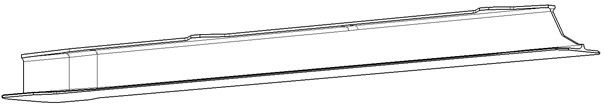
[0032] A material positioning method for laying on a slender flexible mold,

[0033] 1) Soft mold positionin...


PUM

PropertyMeasurementUnit
distanceaaaaaaaaaa

Abstract

The invention discloses a method for positioning a material sheet paved on a slender soft mold. The method comprises the following steps that a laser projector is adopted to project head and tail contour lines of the web surface of the soft mold on a clamping tool and cross-shaped positioning line composed of the center line of the web surface and normal plane short line perpendicular to the center line of the web surface to position, clamp and fix the soft mold; the detection and local adjustment are carried out through positioning detection step; so that the soft mold is positioned to be qualified; then, a material sheet center line marked on the prepreg material sheet lining paper is overlapped with the center line of the web surface of the soft mold projected by the laser projector, and the prepreg material sheet is paved on the soft mold; and finally, the soft mold paved with the prepreg material sheet is used as a core mold and directly combined and positioned to a metal formingauxiliary tool to be cured and formed, and therefore the risk of buckling of fibers of a pre-paving layer in the prepreg material sheet transferring process is avoided. The method is convenient, the clamping tool is simple in structure, the sharing function is achieved, the manufacturing cost is saved, and the method has excellent practical and popularization value.

Description

technical field [0001] The invention relates to a material sheet positioning method for laying on a slender flexible mould. Background technique [0002] I-beams are relatively common reinforced structural parts in composite material parts. They are divided into structural forms such as constant-section I-beams and variable-section I-beams. Word beam parts also have a hyperboloid structure, such as figure 1 and 2 shown. When paving this kind of parts, it is generally divided into four parts: upper, lower, left, and right, that is, the free edge is paved first, then the left vertical edge and the right vertical edge are paved, and then the edges are laminated; in the paving process, it is also necessary to fill the twist filaments, the structure of which is image 3 shown. In composite structural parts with variable-thickness curved surfaces, when the fiber angle of the parts is deviated, the strength, stiffness and stability of the parts will be seriously affected. In ...

Claims


Application Information

Patent Timeline
Patent Type & Authority Applications(China)
IPC IPC(8): B29C70/30
CPCB29C70/30
Inventor 吴青青林丽萍马秀菊郭渊仲睿姚博卿沈科君张旭
Owner 航天海鹰(镇江)特种材料有限公司
Why Eureka
Try Eureka