
Floating type automobile charging pile

A car charging and floating technology, which is applied in electric vehicle charging technology, charging stations, electric vehicles, etc., can solve the problems of damaged charging pile lines, easy corrosion of components, and easy occurrence of safety accidents.

Active Publication Date: 2020-10-27
李楠楠
View PDF7 Cites 2 Cited by
  • Summary
  • Abstract
  • Description
  • Claims
  • Application Information

AI Technical Summary

Problems solved by technology

[0003] When charging piles are used in low-lying areas with a lot of rain, when the drainage system is blocked, it is easy to cause water accumulation. When the water accumulation exceeds the height of the socket of the charging pile, the internal circuit of the charging pile will be damaged. In the event of safety accidents, and long-term use directly exposed to the external environment, in bad weather such as rain and snow, if there is no irregular maintenance and timely repair of minor faults, the outer casing and internal components of the car charging pile are easy to rust and shorten The service life of the car charging pile is shortened, and the frequency of staff repairing the car charging pile is increased, which brings inconvenience to the staff. Therefore, a floating car charging pile is proposed to solve the above problems

Method used


Image

  • Floating type automobile charging pile
  • Floating type automobile charging pile
  • Floating type automobile charging pile

Examples


Embodiment Construction

[0024] In order to make the purpose, features and advantages of the present invention more obvious and understandable, the technical solutions in the embodiments of the present invention will be clearly and completely described below in conjunction with the accompanying drawings in the embodiments of the present invention. Obviously, the following The described embodiments are only some, not all, embodiments of the present invention. Based on the embodiments of the present invention, all other embodiments obtained by persons of ordinary skill in the art without making creative efforts belong to the protection scope of the present invention.

[0025] The technical solutions of the present invention will be further described below in conjunction with the accompanying drawings and through specific implementation methods.

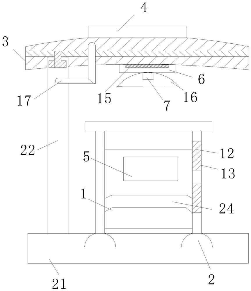
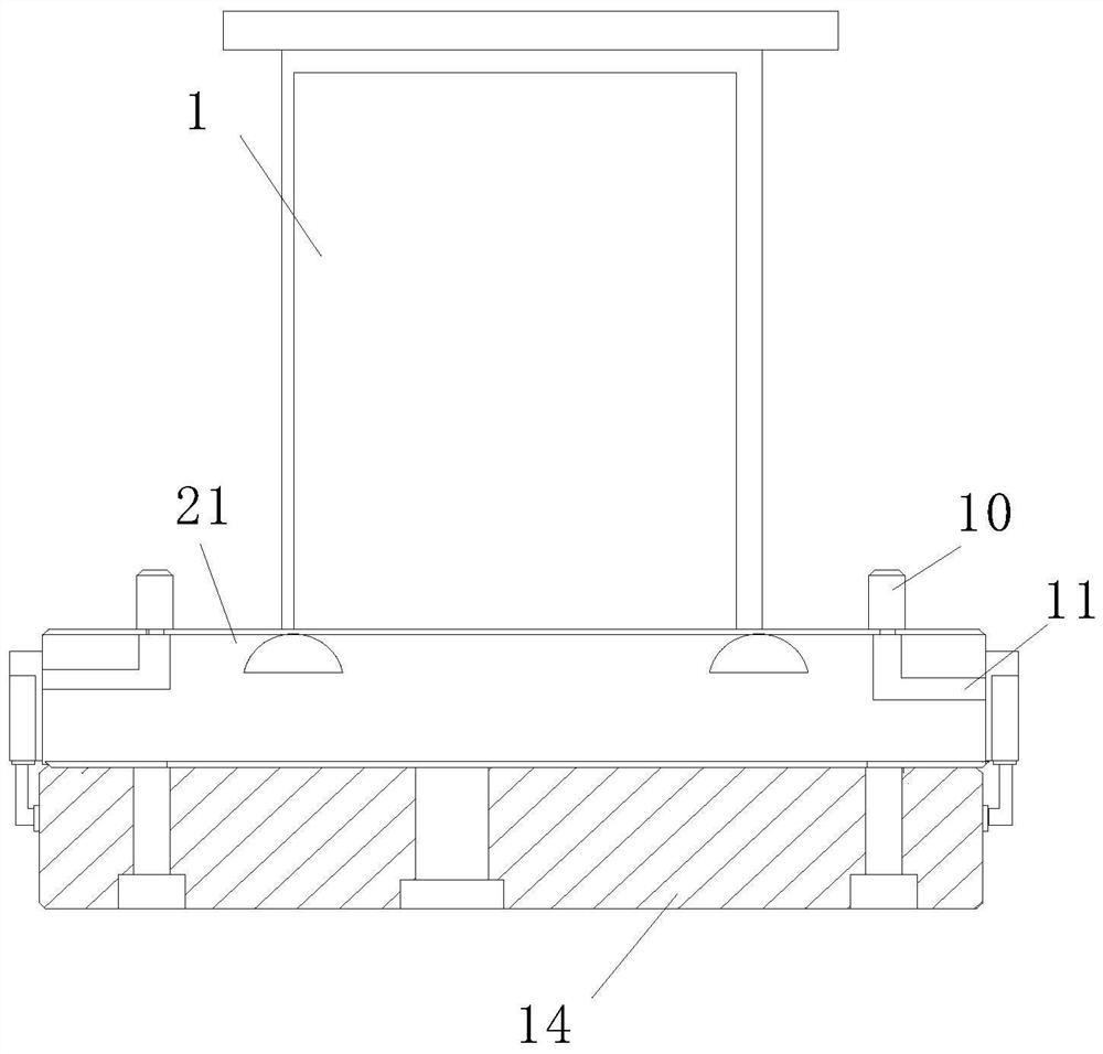
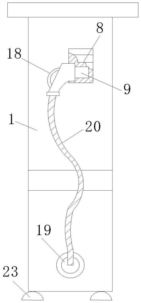
[0026] see Figure 1-4 As shown, a floating car charging pile includes a charging pile 1, a charging gun placement box 8 is fixedly arranged on the top of the...


PUM


Abstract

The invention relates to the technical field of charging piles and especially relates to a floating type automobile charging pile. The charging pile is included. A charging gun placing box is fixedlyarranged at a top end of a left side surface of the charging pile; a charging wire fixing seat is arranged below the charging gun placing box; the charging wire fixing seat is electrically connected with one end of a charging wire; the other end of the charging wire is electrically connected with a charging gun head; the charging gun head is arranged in the charging gun placing box; four groups offixing feet are arranged at the bottom end of the charging pile in a column type; and the fixing feet are clamped with placement grooves formed in the top end of the base. U-shaped buckle plates aremounted on a front end surface and a rear end surface of the charging pile; a worker lifts the automobile charging pile to a certain height through the buckle plate so that the fixing feet mounted atthe bottom are clamped with the placement grooves, and the charging pile and the base are fixed; and meanwhile, a buoyancy tank is filled with a gas through a pedal type pressing air cylinder so thatthe buoyancy tank is lifted by a certain height, and the charging pile is prevented from being damaged when used in a low-lying area with much rainwater.

Description

technical field [0001] The invention relates to the technical field of charging piles, in particular to a floating charging pile for automobiles. Background technique [0002] The function of the charging pile is similar to the fuel dispenser in the gas station. It can be fixed on the ground or wall, and installed in the parking lot or charging station of public buildings and residential areas. It can charge various types of electric vehicles according to different voltage levels. The charging pile The input end of the battery is directly connected to the AC power grid, and the output end is equipped with a charging plug for charging electric vehicles. Charging piles generally provide two charging methods: conventional charging and fast charging. Swipe the card on the computer interactive operation interface to perform operations such as charging method, charging time, and cost data printing. The display screen of the charging pile can display data such as charging amount, c...

Claims


Application Information

Patent Timeline
IPC IPC(8): B60L53/31B60L53/30B60L53/302F21V33/00F21Y115/10
CPCB60L53/31B60L53/30B60L53/302F21V33/00F21Y2115/10Y02T90/16
Inventor 李楠楠孙亮
Owner 李楠楠
Learn More