
A convenient hoisting and handling I-beam transportation device

A technology of transportation device and I-beam, which is applied in the direction of transportation and packaging, load hanging components, and processing of building materials. It can solve problems such as low work efficiency, poor flexibility, and danger, and achieve improved construction efficiency, convenient disassembly, and The effect of great flexibility

Active Publication Date: 2021-02-05
济宁天华市政园林有限公司
View PDF5 Cites 0 Cited by
  • Summary
  • Abstract
  • Description
  • Claims
  • Application Information

AI Technical Summary

Problems solved by technology

[0002] In building construction, there are many application requirements for I-beams. At present, steel wire ropes are generally used for hoisting I-beams. Using this hoisting method is time-consuming and laborious, and the work efficiency is low. Moreover, the contact area between the wire rope and I-beams is small, and friction Small, if the center of gravity shifts slightly or is hit during lifting, the I-beam is easy to slip, which is very dangerous. There is also a hoisting method that directly drills holes on the flat plate of the I-beam, through the holes on the I-beam. Rope hooks or direct hooks, although this method can solve the problem of weight loss of the I-beam in the air, but the processing technology of the I-beam is more cumbersome and the cost increases
[0003] In addition, for the transportation of I-beams in the construction site, the existing transportation method is to use trucks or other transportation vehicles, which is very inconvenient and poor in flexibility in some places with dense buildings.

Method used


Image

  • A convenient hoisting and handling I-beam transportation device
  • A convenient hoisting and handling I-beam transportation device
  • A convenient hoisting and handling I-beam transportation device

Examples


Embodiment Construction

[0030] The technical solutions in the embodiments of the present invention will be clearly and completely described below in conjunction with the accompanying drawings in the embodiments of the present invention. Obviously, the described embodiments are only some of the embodiments of the present invention, not all of them. Based on The embodiments of the present invention and all other embodiments obtained by persons of ordinary skill in the art without making creative efforts belong to the protection scope of the present invention.

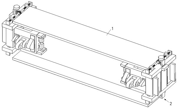
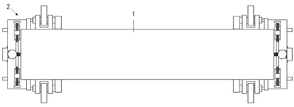
[0031] Depend on Figure 1 to Figure 10As shown, an I-beam transportation device that is convenient for hoisting and handling includes a pair of transportation device assemblies 2, and the transportation device assembly 2 includes a mobile drive base plate 21 and a pair of automatic clamping arms 22. The mobile drive base plate 21 The center of the front side wall of the front side wall is provided with a central card slot 211 and a pair of mutu...


PUM


Abstract

The invention discloses an I-beam transporting device beneficial for hanging and carrying. The I-beam transporting device comprises a pair of transporting device assemblies. Each transporting device assembly comprises a movable driving bottom plate and a pair of automatic clamping arms, wherein a pair of movable bases are movably disposed in the movable driving bottom plate, the automatic clampingarms are inserted in the corresponding movable bases, a clamping block, a pair of supporting top plates, a hanging ring and a fixture block are disposed on each automatic clamping arm, when the hanging rings rotate, the clamping blocks press the side walls of a vertical plate of I-beam, the supporting top plates eject the bottom face of a top plate of the I-beam, the fixture blocks are clamped inthe movable bases, and movable wheels are disposed on the front side wall of the movable driving bottom plate. The I-beam transporting device has the advantages that under the weight of the I-beam, the hanging rings rotate, the clamping blocks on the two sides thereby can firmly clamp the middle vertical plate of the I-beam, by placing the two movable driving bottom plates on the bottom of the I-beam, the I-beam can be transported, and thus the I-beam transporting device is diversified in function, high in flexibility and easy to operate.

Description

technical field [0001] The invention relates to the technical field of building material transportation equipment, in particular to an I-beam transportation device that is convenient for hoisting and handling. Background technique [0002] In building construction, there are many application requirements for I-beams. At present, steel wire ropes are generally used for hoisting I-beams. Using this hoisting method is time-consuming and laborious, and the work efficiency is low. Moreover, the contact area between the wire rope and I-beams is small, and friction Small, if the center of gravity shifts slightly or is hit during lifting, the I-beam is easy to slip, which is very dangerous. There is also a hoisting method that directly drills holes on the flat plate of the I-beam, through the holes on the I-beam. Rope hooks or direct hooks, although this method can solve the problem of weight loss of the I-beam in the air, but the processing technology of the I-beam is more cumberso...

Claims


Application Information

Patent Timeline
Patent Type & Authority Patents(China)
IPC IPC(8): B66C1/10B66C1/42B66C1/64B66C13/04E04G21/16
CPCB66C1/10B66C1/42B66C1/422B66C1/64B66C13/04E04G21/162
Inventor 詹海霞范丰李卫华董荣宝
Owner 济宁天华市政园林有限公司
Learn More