Calcium carbide cooling and heat dissipation device

A heat-dissipating device and calcium carbide technology, applied in the field of heat-dissipating devices and calcium carbide cooling and heat-dissipating devices, can solve the problems of poor cooling effect and the like

Pending Publication Date: 2020-10-27
ZHEJIANG RONGRUN MACHINERY CO LTD
View PDF1 Cites 3 Cited by
  • Summary
  • Abstract
  • Description
  • Claims
  • Application Information

AI Technical Summary

Problems solved by technology

However, there are still technical problems such as poor cooling effect

Method used


Image

  • Calcium carbide cooling and heat dissipation device
  • Calcium carbide cooling and heat dissipation device
  • Calcium carbide cooling and heat dissipation device

Examples


Embodiment 1

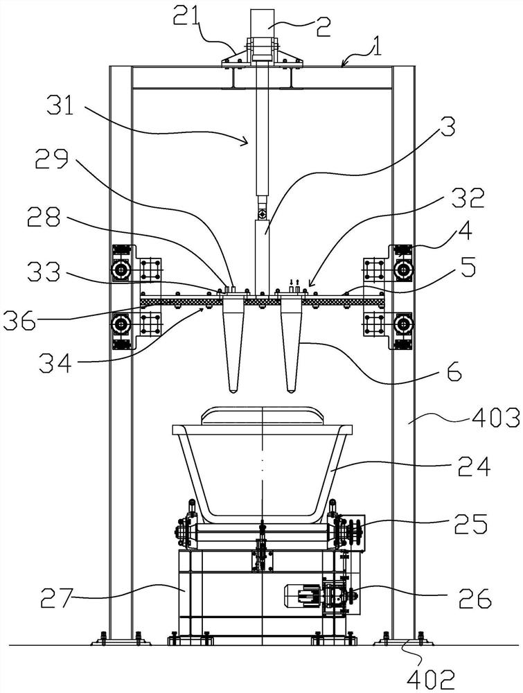
[0027] Such as Figure 1-4 As shown, the calcium carbide cooling and heat dissipation device includes a frame 1 and a support frame 5 arranged on the frame 1. A lifting mechanism capable of driving the support frame 5 up and down in the vertical direction is provided between the support frame 5 and the frame 1. 31. The support frame 5 is provided with at least one insert body 6, and the insert body 6 is provided with a heat dissipation component. The heat dissipation component includes a heat exchange cavity arranged in the insert body 6, and the insert body 6 is provided with a heat exchange cavity communicating with the heat exchange cavity. Gas / liquid inlet 29 and gas / liquid outlet 28. After the insertion body 6 is inserted into the calcium carbide, the gas or liquid absorbed in the heat exchange cavity enters the heat exchanger through the gas / liquid outlet 28 for heat exchange and cooling, and then flows back into the heat exchange cavity through the gas / liquid inlet 29.

...

Embodiment 2

[0050] Such as Figure 5 As shown, the structure, principle, and embodiment steps of this embodiment are similar to those of Embodiment 1, and the differences are:

[0051] The heat exchange cavity includes a heat exchange channel 35 arranged in a spiral shape in the insert 6. One end of the heat exchange channel 35 is connected with the gas / liquid inlet 29 and the other end is connected with the gas / liquid outlet 28.

[0052] The working principle is: when the motor 26 is started, the hopper 24 placed on the raceway 25 is driven to move. When the hopper 24 placed on the raceway 25 moves below the support frame 5, the motor 26 stops, and the telescopic cylinder 2 drives the support through the connecting rod 3. The plate 5 moves downwards so that the insert 6 at the lower end of the support plate 5 is inserted into the calcium carbide in the hopper 24, the gas or liquid that absorbs heat in the heat exchange cavity enters the heat exchanger through the gas / liquid outlet 28 for heat ...

Embodiment 3

[0054] Such as Image 6 , 7 As shown, the structure, principle, and embodiment steps of this embodiment are similar to those of embodiment 1, except that: the inner end of the gas / liquid inlet 29 is fixed with an inlet pipe 291 located in the cavity 7, and the lower end of the inlet pipe 291 extends To the bottom of the cavity 7, an arc-shaped guide tube 292 extending outward is provided at the lower end of the inlet tube 291, and the arc-shaped guide tube 292 gradually slopes upward from the inner end to the outer end. The arc-shaped guide tube 292 can form a vortex in the cavity 7.


PUM


Abstract

The invention belongs to the technical field of calcium carbide production, and relates to a heat dissipation device, in particular to a calcium carbide cooling and heat dissipation device. The devicecomprises a rack and a support frame arranged on the rack, a lifting mechanism capable of driving the support frame to ascend and descend in the vertical direction is arranged between the support frame and the rack, at least one inserting body is arranged on the support frame, a heat dissipation assembly is arranged on the inserting body, the heat dissipation assembly comprises a heat exchange cavity formed in the inserting body, and a gas/liquid inlet and a gas/liquid outlet which are communicated with a heat exchange cavity are formed in the inserting body. Compared with the prior art, thecalcium carbide cooling and heat dissipation device has the advantages that: 1, the design is reasonable, and the cooling effect can be improved.

Description

Technical field [0001] The invention belongs to the technical field of calcium carbide production, and relates to a heat dissipation device, in particular to a calcium carbide cooling and heat dissipation device. Background technique [0002] China is the country with the largest production and consumption of calcium carbide in the world. The molten calcium carbide temperature is as high as 1800-1900 degrees when it is out of the furnace, and its enthalpy is high and the heat is large. In the current calcium carbide production plant, after the molten calcium carbide is discharged from the furnace, it is placed in figure 1 Inside the open calcium carbide pot shown. Because the existing calcium carbide pot is a trapezoidal longitudinal section with a large upper and a small bottom, an open mouth without a cover, and a smooth wall surface, the molten calcium carbide can only be cooled by natural cooling for a long time (20-14 hours) or forced cooling by blast It takes a long time ...

Claims


Application Information

Patent Timeline
Patent Type & Authority Applications(China)
IPC IPC(8): C01B32/942F27D15/02
CPCC01B32/942F27D15/02
Inventor 边均明楼骏绯周高永徐建青蒋海明
Owner ZHEJIANG RONGRUN MACHINERY CO LTD
Why Eureka
Try Eureka