
Press roll of paper machine

A paper machine and pressure roller technology, applied in the field of paper machine pressure rollers, can solve the problems of small storage space, difficult cleaning, limited operating environment, etc., and achieve the effects of keeping clean and dry, reducing the risk of electric leakage, and avoiding water and rust

Inactive Publication Date: 2020-10-27
严一涛
View PDF0 Cites 2 Cited by
  • Summary
  • Abstract
  • Description
  • Claims
  • Application Information

AI Technical Summary

Problems solved by technology

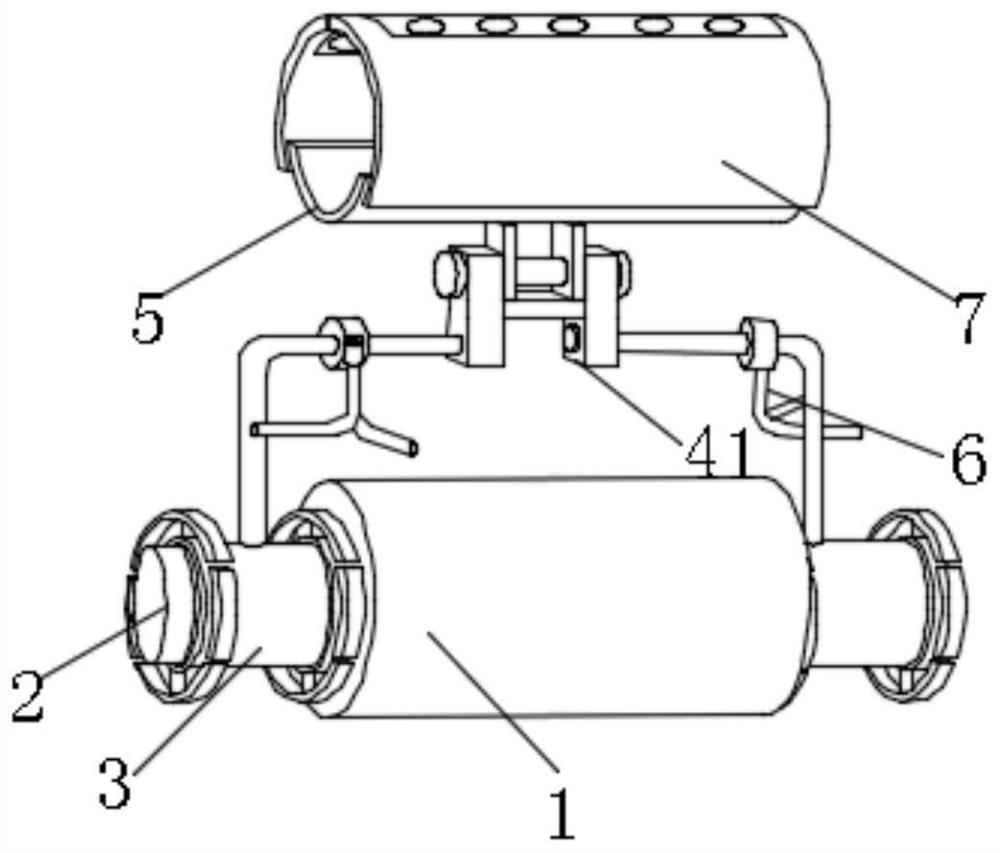
[0003] In the process of realizing the present invention, the inventor found that there are at least the following problems in the prior art that have not been solved: 1. When the pressure roller is in use, during the rolling process, the roller body squeezes out the moisture in the pulp, and the roller body is repeatedly rotating , Splash a certain amount of water, and the water will splash to the connection between the roller shaft and the roller body and the connection between the roller shaft and the motor, which is easy to rust and affect the rotation; 2. The surface of the roller body used for a long time will be contaminated with too much If the moisture and residual pulp are not cleaned in time, the surface will be corroded by moisture, and the pulp will stick to the surface of the roller body. After a long time, it will be more difficult to clean after air drying; 3. The paper machine is generally stored in the workshop, and its operating environment is limited. The storage space between them is small, easy to bump, and exposed to the outside for a long time, the surface of the roller body is easily contaminated with dust; 4. The structure of the roller body needs to be repaired before use. The traditional roller body structure is fixed, so it is inconvenient to repair it

Method used


Image

  • Press roll of paper machine
  • Press roll of paper machine
  • Press roll of paper machine

Examples


Embodiment Construction

[0031] The technical solutions of the present invention will be clearly and completely described below in conjunction with the embodiments. Obviously, the described embodiments are part of the embodiments of the present invention, but not all of them. Based on the embodiments of the present invention, all other embodiments obtained by persons of ordinary skill in the art without making creative efforts belong to the protection scope of the present invention.

[0032] In describing the present invention, it is to be understood that the terms "center", "longitudinal", "transverse", "length", "width", "thickness", "upper", "lower", "front", " Back", "Left", "Right", "Vertical", "Horizontal", "Top", "Bottom", "Inner", "Outer", "Clockwise", "Counterclockwise", etc. or The positional relationship is based on the orientation or positional relationship shown in the drawings, which is only for the convenience of describing the present invention and simplifying the description, rather t...


PUM


Abstract

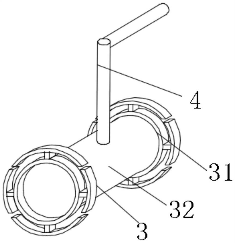
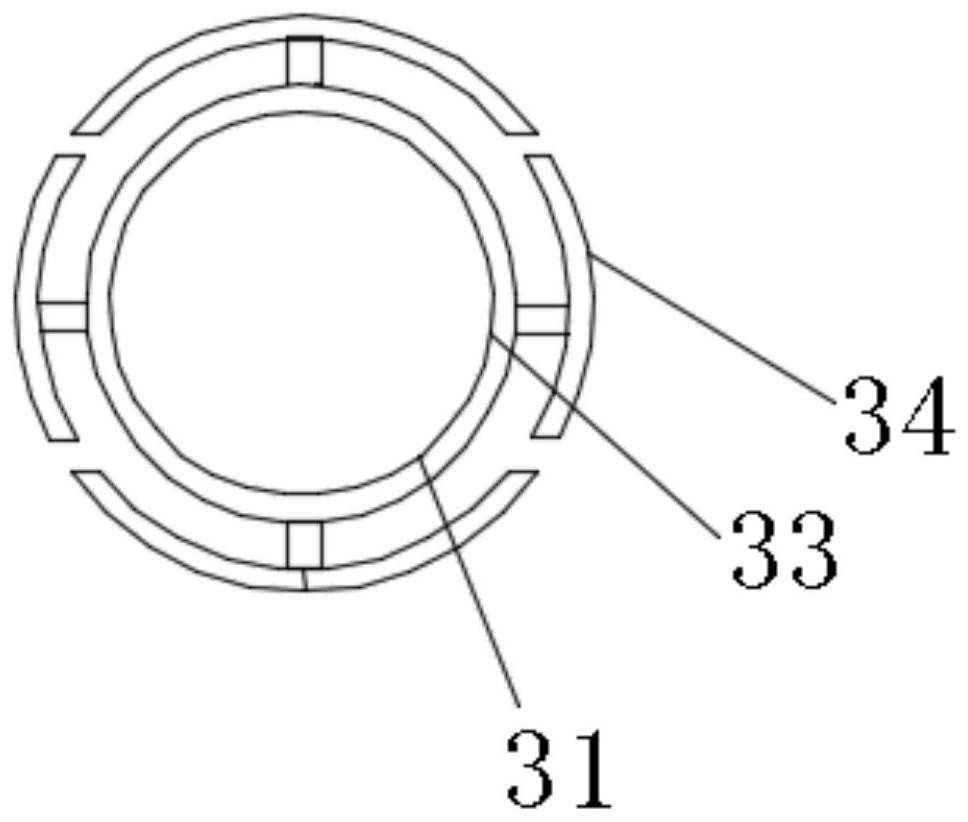
The invention provides a press roll of a paper machine. The press roll comprises a roller body and two roller shafts. The two roller shafts are fixedly installed at the positions, close to the middle,of the outer surfaces of the two sides of the roller body. And the outer surfaces of the two roller shafts are movably connected with a protection mechanism, which is composed of two limiting ring mechanisms and a long cylinder; the two limiting ring mechanisms are fixedly installed on the outer surfaces of the two sides of the long cylinder, each limiting ring is composed of a circular ring andfour T-shaped rotating blocks. According to the invention, the roller shaft can be prevented from rusting in water; and moreover, the danger of electric leakage can be reduced, moisture generated whenthe roller body rolls paper pulp can be erased, the outer surface of the roller body is kept clean and dry, the protection on the roller body is enhanced, dust on the outer surface of the roller bodyis properly blocked, the outer surface of the roller body can be prevented from being abraded and collided, the roller body structure can be conveniently erected, and thus the roller body is convenient to maintain and detect.

Description

technical field [0001] The invention relates to the technical field of press rolls, in particular to a paper machine press roll. Background technique [0002] During the use of the paper machine, it is often necessary to use rollers. The function of the press section of the paper machine is to dehydrate the wet paper. The press roll of the paper machine is the main component of the press device. It is mainly used to squeeze the pulp on the felt, extrude moisture in the pulp. [0003] In the process of realizing the present invention, the inventor found that there are at least the following problems in the prior art that have not been solved: 1. When the pressure roller is in use, during the rolling process, the roller body squeezes out the moisture in the pulp, and the roller body is repeatedly rotating , Splash a certain amount of water, and the water will splash to the connection between the roller shaft and the roller body and the connection between the roller shaft and ...

Claims


Application Information

Patent Timeline
Patent Type & Authority Applications(China)
IPC IPC(8): D21F3/08
CPCD21F3/08
Inventor 严一涛刘童童
Owner 严一涛
Learn More