
Steel box beam and concrete column hinged joint and construction method thereof

A technology of concrete column and steel box girder, applied in construction, building structure and other directions, can solve the problems of inconsistency, free rotation of restricted beam ends, hoisting in place, and the difficulty of high-altitude installation operations, etc., to solve stress concentration, ensure components Stress requirements, effects of improved reliability and implementability

Pending Publication Date: 2020-10-27
CHINA CITY ENVIRONMENT PROTECTION ENGINEERING LIMITED COMPANY
View PDF0 Cites 1 Cited by
  • Summary
  • Abstract
  • Description
  • Claims
  • Application Information

AI Technical Summary

Problems solved by technology

[0004] (1) The welding method of the web of the steel beam and the buried slab of the concrete column is generally used for I-shaped cross-section beams. For box-shaped cross-sections with multiple webs, the connection method will be restricted by the width of the column; when the beam When the length or self-weight is large, the difficulty of hoisting in place and high-altitude installation will increase significantly
[0005] (2) In the way of directly placing the steel beam on the column side corbel (or column top), the welding of the beam end support plate and the embedded plate on the corbel (or column top) needs enough welding space; when the corbel (or column top) or the top of the column) when the length of the support is too long, this connection may also restrict the free rotation of the beam end, resulting in inconsistency with the calculation assumptions

Method used


Image

  • Steel box beam and concrete column hinged joint and construction method thereof
  • Steel box beam and concrete column hinged joint and construction method thereof
  • Steel box beam and concrete column hinged joint and construction method thereof

Examples


Embodiment Construction

[0035] The following will clearly and completely describe the technical solutions in the embodiments of the present invention with reference to the accompanying drawings in the embodiments of the present invention. Obviously, the described embodiments are only some, not all, embodiments of the present invention. Based on the embodiments of the present invention, all other embodiments obtained by persons of ordinary skill in the art without making creative efforts belong to the protection scope of the present invention.

[0036] In describing the present invention, it is to be understood that the terms "center", "upper", "lower", "front", "rear", "left", "right", "vertical", "horizontal", The orientations or positional relationships indicated by "top", "bottom", "inner", "outer", etc. are based on the orientations or positional relationships shown in the drawings, and are only for the convenience of describing the present invention and simplifying the description, rather than in...


PUM


Abstract

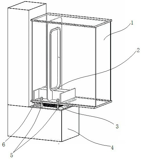
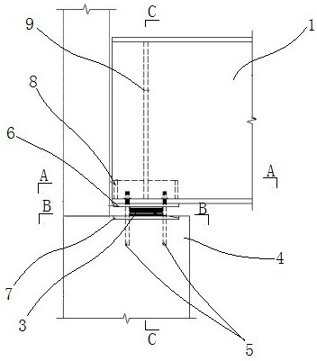
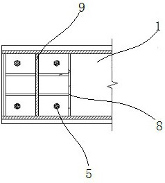
The invention provides a steel box beam and concrete column hinged joint and a construction method thereof. The steel box beam and concrete column hinged joint comprises a concrete column and a steelbox beam. The end of the steel box beam is located on the column side bracket of the concrete column, and a rubber support is arranged between the steel box steam and the column side bracket. The steel box beam and the column side bracket are fixed through multiple foundation bolts. An inner supporting assembly is arranged in the steel box beam and located in the foundation bolt installation area.According to the steel box beam and concrete column hinged joint, the rubber support and the inner supporting assembly are adopted to jointly connect the steel box beam and the concrete column, so that shear force transmitted by the steel box beam can be transmitted, rotation deformation of the steel box beam in the bent direction is reasonably released, and reliability and implementation performance of joint connection are improved; and meanwhile, a bolted fixation manner is adopted, on-site fixation of the steel box beam and the concrete column is adjusted into the steel box beam, on-site welding operation is canceled, the space in the steel box beam is fully utilized, the space problem of on-site installation is solved, and on-site construction quality and component stress requirementsare effectively guaranteed.

Description

technical field [0001] The invention belongs to the technical field of building construction, and in particular relates to a steel box girder and a concrete column hinge joint and a construction method thereof. Background technique [0002] When the concrete column and the steel beam are hingedly connected, the web of the steel beam is generally welded to the side embedded plate of the concrete column, or the beam is directly placed on the column side corbel (or column top). The first method is to weld a connecting plate on the column side buried plate, and connect the connecting plate and the steel beam web through high-strength bolts or welds; the second method is similar to the connection form of the crane beam support, that is, at the beam end Set the flat plate or flange plate, and then weld the plate or flange plate to the embedded plate on the corbel (or column top) of the concrete column. [0003] However, it can be seen from the hinged connection structure of concr...

Claims


Application Information

Patent Timeline
Patent Type & Authority Applications(China)
IPC IPC(8): E04B1/18E04B1/58
CPCE04B1/18E04B1/185
Inventor 邓余海熊敬超金鑫刘耀祝远驰
Owner CHINA CITY ENVIRONMENT PROTECTION ENGINEERING LIMITED COMPANY
Learn More