Check patentability & draft patents in minutes with Patsnap Eureka AI!

Inertial positioning method for steam turbine jigger

An inertial positioning and steam turbine technology, applied in the field of inertial positioning of steam turbine barring, can solve problems such as cumbersome, gear wear, and uncontrollable rotation angles

Active Publication Date: 2020-10-27
HUANENG SHANDONG SHIDAOBAY NUCLEAR POWER CO LTD
View PDF8 Cites 0 Cited by
  • Summary
  • Abstract
  • Description
  • Claims
  • Application Information

AI Technical Summary

Problems solved by technology

And because the rotor will generate inertia after it rotates, when the jog button is operated on the local control box of the barring, the rotation angle will be uncontrollable due to the inertial rotation of the rotor; After the turning device is disengaged, it needs to be re-engaged manually. The operation time is long and cumbersome. Automatic trip event occurs

Method used


Image

  • Inertial positioning method for steam turbine jigger

Examples


Embodiment Construction

[0015] The present invention is described in further detail below in conjunction with accompanying drawing.

[0016] see figure 1 , an inertial positioning method for a steam turbine barring, specifically comprising the following steps:

[0017] Step 1. Straighten the large shaft of the steam turbine: start the lubricating oil and jacking oil system of the steam turbine cranking, and wait for the steam turbine jacking oil system to run stably, that is, when the oil pressure has no band and there is no leakage on site, start the cranking Start continuous cranking on the control cabinet until the eccentricity of the major shaft falls within the rated range (≤20μm);

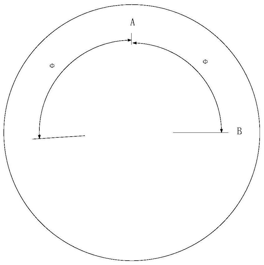
[0018] Step 2. Preset a barring stop point A, crank for multiple turns continuously, and then stop barring at this point. When the main shaft of the steam turbine stops completely, record the stop point of the main shaft of the steam turbine and the preset stop point. The deflection angle Φ of point A is based on ...


PUM


Abstract

The invention discloses an inertial positioning method for a steam turbine jigger. The method comprises the following steps of first straightening a main shaft of the steam turbine, presetting a stoppoint A, cranking the jigger continuously for multiple laps, stopping the cranking at the stop point A, recording a deflection angle theta between the stop point of the main shaft of the steam turbineand the preset stop point A when the main shaft of the steam turbine is completely stopped, and getting a new stop point B by the reverse deflection angle theta by taking the stop point A as the reference; starting the cranking device, stopping the jigger device at the stop point B after the main shaft of the steam turbine rotates the same number of turns as in the step 2, and making the main shaft of the steam turbine turn over 180 degrees when the main shaft of the steam turbine stops rotating. The inertial positioning method has the advantages of simple operation, accurate positioning andpracticality as well as high efficiency.

Description

technical field [0001] The invention relates to a method for operating a steam turbine barring, in particular to an inertial positioning method for a steam turbine barring. Background technique [0002] The main function of the steam turbine barring device is to turn the entire rotor before starting or after stopping the unit to avoid permanent deformation of the rotor. The steam turbine needs to be cranked regularly during the maintenance period, for example, the steam turbine rotor is rotated 180° every 14 days to reduce the eccentricity of the steam turbine rotor and ensure that the steam turbine rotor is always in good condition. [0003] The main work during the turning of the steam turbine is to determine the rotation angle of the rotor, that is, to determine the stop position of the rotor, so as to ensure that the initial state of the rotor has rotated 180° relative to the turning; Depending on the state, the time for the rotor to rotate and the time for idling due t...

Claims


Application Information

Patent Timeline
Patent Type & Authority Applications(China)
IPC IPC(8): F01D25/34
CPCF01D25/34Y02E10/20
Inventor 赵敬锴常重喜王磊李小龙崔鹏
Owner HUANENG SHANDONG SHIDAOBAY NUCLEAR POWER CO LTD
Features
  • R&D
  • Intellectual Property
  • Life Sciences
  • Materials
  • Tech Scout
  • Unparalleled Data Quality
  • Higher Quality Content
  • 60% Fewer Hallucinations
Learn More