Novel quick coupling device for pressure gauge

A technology of joint device and pressure gauge, which is applied in the direction of measuring device, measuring fluid pressure, instrument, etc., can solve the problems of the pressure gauge coming out, the inability to press the pressure gauge and the movable sleeve of the sealing ring, and the difficulty in pressing.

Pending Publication Date: 2020-10-27
江苏丰仪同创互联科技有限公司
View PDF1 Cites 1 Cited by
  • Summary
  • Abstract
  • Description
  • Claims
  • Application Information

AI Technical Summary

Problems solved by technology

[0005] However, the above-mentioned structure has a major problem in the actual use process. When the quick joint is connected to the pressure gauge, when the pressure gauge is fed with high-pressure and low-pressure media, the tightness between the quick joint and the pressure gauge is poor, and the pressure gauge may even appear from the pressure gauge at high pressure. The specific reasons for the detachment of the quick connector are as follows:
[0006] The opening of the claw is to drive the ejector rod by pushing the fulcrum, and further push the tension sleeve to move upward, thereby pushing the claw to open. When the pressure gauge is installed, the seal is through the contact between

Method used


Image

  • Novel quick coupling device for pressure gauge
  • Novel quick coupling device for pressure gauge
  • Novel quick coupling device for pressure gauge

Examples


Embodiment Construction

[0020] The present invention will be further described below in conjunction with the accompanying drawings. The following examples are only used to illustrate the technical solution of the present invention more clearly, but not to limit the protection scope of the present invention.

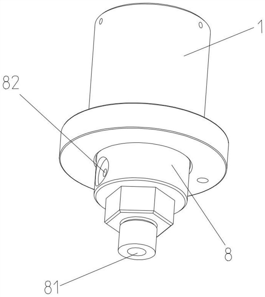
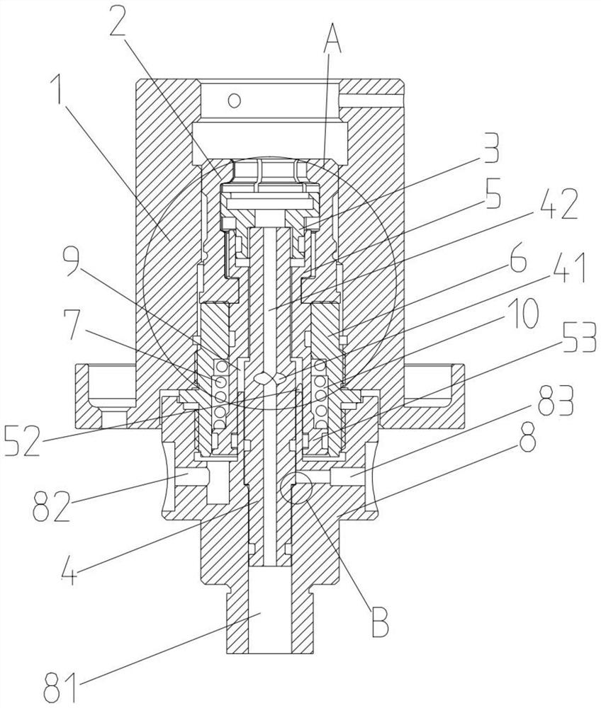
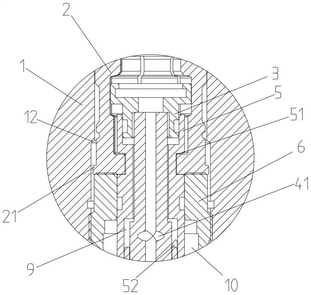
[0021] A new type of quick connector device for pressure gauges, comprising an outer casing 1, claws 2, movable sleeve 3 of a sealing ring, a floating inner tube 4, a tightening sleeve 5, a sealing pressure bearing sleeve 6 and a base 8, and the floating inner tube 4 is set In the tension sleeve 5 and slidingly matched with the tension sleeve 5, the top of the floating inner tube 4 is provided with a sealing ring movable sleeve 3, and the upper part of the tension sleeve 5 is provided with a claw 2, and the tension sleeve 5 The lower part is provided with a sealing pressure-bearing sleeve 6, and the tensioning sleeve 5 can be rotatably matched with the claw 2. The tensioning sleeve 5 is slidingl...


PUM


Abstract

The invention relates to an improvement on a connecting joint device and particularly relates to a novel quick coupling device for a pressure gauge, the clamping action, the sealing action, the pressure supply action and the dismounting action of the pressure gauge can be achieved through on-off control over a calibration gas circuit, a clamping and loosening driving gas circuit and a sealing gascircuit, that pressure can be stably supplied while the pressure gauge is clamped is guaranteed, and dismounting is convenient. The device comprises an outer sleeve (1), a clamping jaw (2), a sealingring movable sleeve (3), a floating inner pipe (4), a tensioning sleeve (5), a sealing pressure-bearing sleeve (6) and a base (8), wherein the floating inner pipe (4) is arranged in the tensioning sleeve (5) and is in sliding fit with the tensioning sleeve (5), the sealing ring movable sleeve (3) is arranged at the top of the floating inner pipe (4), the clamping jaw (2) is arranged on an upper portion of the tensioning sleeve (5), the sealing pressure-bearing sleeve is arranged on a lower portion of the tensioning sleeve, and the tensioning sleeve can be in rotating fit with the clamping jaw.

Description

technical field [0001] The invention relates to an improvement to a connecting joint device, in particular to a novel quick joint device for a pressure gauge. Background technique [0002] A pressure gauge is an instrument that uses elastic elements as sensitive elements to measure and indicate pressure higher than the environment. It is widely used, and it pervades almost all industrial processes and scientific research fields. It can be seen everywhere in the fields of heat pipe network, oil and gas transmission, water supply and gas supply system, vehicle maintenance shop, industrial process control and technical measurement. Especially in the occasions where the pressure gauge needs to be clamped frequently on the pressure gauge verification device, due to the high mechanical strength and convenient production of the elastic sensitive element of the mechanical and digital display pressure gauge, the mechanical and digital display pressure gauge be more and more widely u...

Claims


Application Information

Patent Timeline
IPC IPC(8): G01L19/00G01L19/14
CPCG01L19/0007G01L19/14
Inventor 殷勇陈兆志陈光华
Owner 江苏丰仪同创互联科技有限公司
Why Eureka
Try Eureka