Bolt looseness sensing device based on piezoelectric traction effect

A technology of bolt loosening and traction effect, which is applied in the direction of using electric/magnetic devices to transmit sensing components, measuring devices, and testing of mechanical components, and can solve problems such as high energy consumption, high cost, and complex design of monitoring technology

Active Publication Date: 2020-10-27
HARBIN INST OF TECH
View PDF13 Cites 2 Cited by
  • Summary
  • Abstract
  • Description
  • Claims
  • Application Information

AI Technical Summary

Problems solved by technology

[0004] In order to solve the problems of complex design, high energy consumption, high cost and low sensitivity of the existin

Method used


Image

  • Bolt looseness sensing device based on piezoelectric traction effect
  • Bolt looseness sensing device based on piezoelectric traction effect
  • Bolt looseness sensing device based on piezoelectric traction effect

Examples


specific Embodiment approach 1

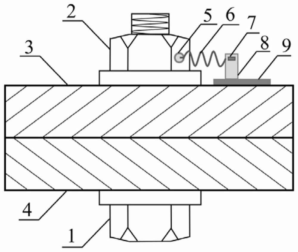
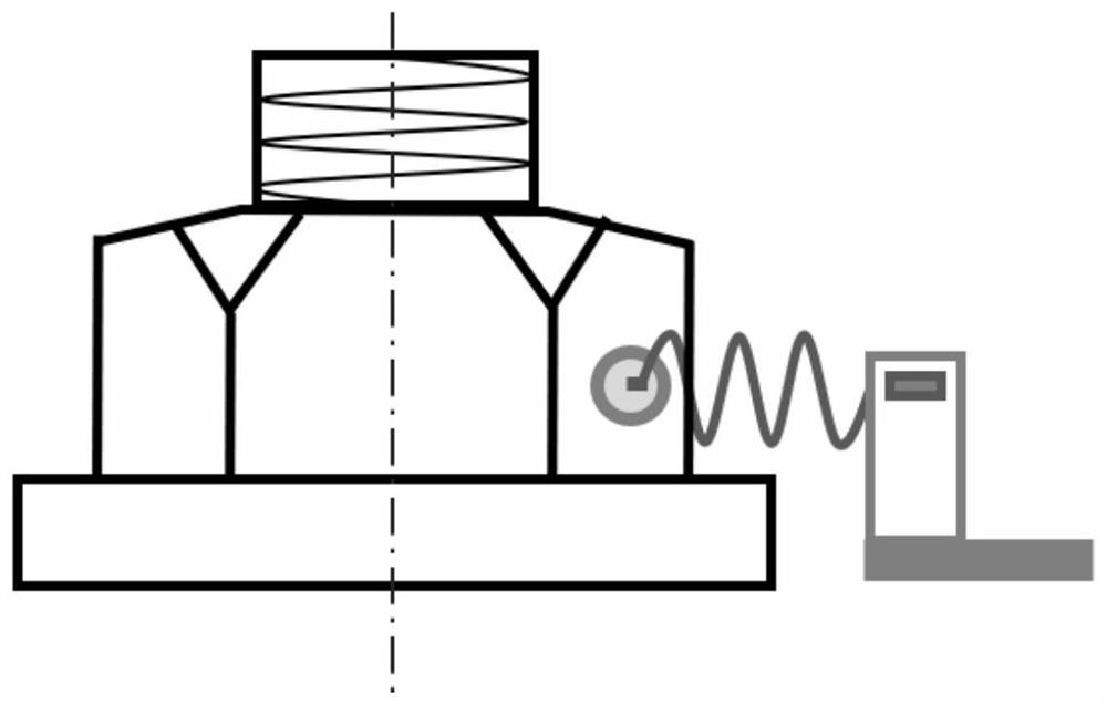
[0022] Specific implementation mode one: the following combination Figure 1 to Figure 3 , Figure 5 and Figure 6 To illustrate this embodiment, a piezoelectric traction effect bolt looseness sensing device described in this embodiment includes a connecting end piece 5, a spring 6, a piezoelectric piece 7, a metal shrapnel 8, a bottom bracket 9 and a signal processing module;

[0023] A signal processing module is embedded inside the bottom bracket 9, and a metal shrapnel 8 is vertically arranged on the upper surface of the bottom bracket 9. The piezoelectric sheet 7 is attached to the upper end of the metal shrapnel 8, and the suspended end of the metal shrapnel 8 is connected to the tail end of the spring 6. The head end is fixedly provided with a connection end piece 5, and the connection end piece 5 is pressed against the side of the nut;

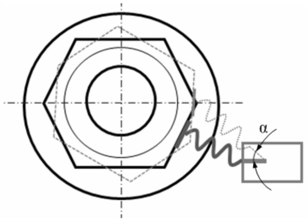
[0024] When the bolt is loose, the connecting end piece 5 swings along with the nut, the connecting end piece 5 drives the spring 6...

specific Embodiment approach 2

[0030] Specific implementation mode two: the following combination Figure 4 This embodiment is described. The difference between this embodiment and Embodiment 1 is that the head end of the spring 6 connected to the connecting end piece 5 is an equidistant helical structure, and is preferably integrally formed. The equidistant helical structure of the spring has an excellent stable structure and a large contact surface, making the connection more reliable.

[0031] The end of the conventional spring is a single circle, and the truncation often has a protruding end, which is not conducive to the connection with the connecting end piece 5 and the smoothness of being pressed on the nut.

[0032] In this embodiment, the first end of the spring 6 is changed to an equidistant helical structure to increase the contact area with the connecting end piece 5, so that the force transmitted by the spring 6 can be more smoothly and positively supported on the nut 2 through the connecting e...


PUM


Abstract

The invention discloses a bolt looseness sensing device based on a piezoelectric traction effect, belongs to the field of mechanical fastener monitoring, and aims to solve problems of complex design,high energy consumption, high cost, low sensitivity and the like in the conventional monitoring technology. The device comprises a connecting end sheet, a spring, a piezoelectric sheet, a metal elastic sheet, a bottom support and a signal processing module, wherein the signal processing module is embedded in the bottom support, a metal elastic piece is vertically arranged on an upper end face of the bottom support, a piezoelectric piece is attached to an upper end of the metal elastic piece, a suspended end of the metal elastic piece is connected with a tail end of a spring, and a connecting end piece is fixedly arranged at a head end of the spring and pressed on a side face of the nut. When the bolt is loosened, the connecting end piece swings along with the nut, the connecting end piecedrives the spring to stretch out and draw back, the traction force generated by stretching out and drawing back of the spring exerts load on the metal elastic piece pasted with the piezoelectric pieceto enable the metal elastic piece to be bent, bending deformation induces the piezoelectric piece to generate piezoelectric signals, and the signal processing module receives the piezoelectric signals to achieve sensing of bolt loosening.

Description

technical field [0001] The invention relates to a device for monitoring bolt looseness, which belongs to the field of mechanical fastener monitoring. Background technique [0002] As one of the most common connection methods, bolt connection widely exists in various fields of national production, such as various constructions, railways, wind power generation, machinery, instruments and aerospace devices, providing great support for the connection and assembly of devices and components. convenient. Under normal circumstances, there are two main reasons for the failure of bolts: fracture and loosening, among which loosening is the most common problem. While loose bolts are a common occurrence and often overlooked, small problems can often lead to catastrophe. If the tightening state of the bolt is light, it will affect the working performance of the equipment, such as abnormal vibration of the equipment, damage to the components, etc., and if it is serious, it will cause cas...

Claims


Application Information

Patent Timeline
IPC IPC(8): G01M13/00G01D5/14
CPCG01M13/00G01D5/14
Inventor 潘振路晓艳
Owner HARBIN INST OF TECH
Why Eureka
Try Eureka