Laser radar optical system and aberration compensation method thereof

An optical system and lidar technology, applied in radio wave measurement systems, electromagnetic wave re-radiation, utilization of re-radiation, etc. problem, to achieve the effect of low cost

Pending Publication Date: 2020-10-27
CHANGZHOU XINRUIDE INSTR
View PDF0 Cites 0 Cited by
  • Summary
  • Abstract
  • Description
  • Claims
  • Application Information

AI Technical Summary

Problems solved by technology

Due to the aberration brought by the annular light hood, it brings certain difficulties to the aberration correction of the optical design of the transmitting and receiving objective lens. If the aberration of the objective lens is too large, it will directly affect the measurement distance. Although aspheric and cylindrical surfaces can be used The phase difference is corrected in the form of one-piece lens, but the processing cost of aspheric and cylindrical one-piece lens in China is high and the technology is immature

Method used


Image

  • Laser radar optical system and aberration compensation method thereof
  • Laser radar optical system and aberration compensation method thereof
  • Laser radar optical system and aberration compensation method thereof

Examples


Embodiment 1

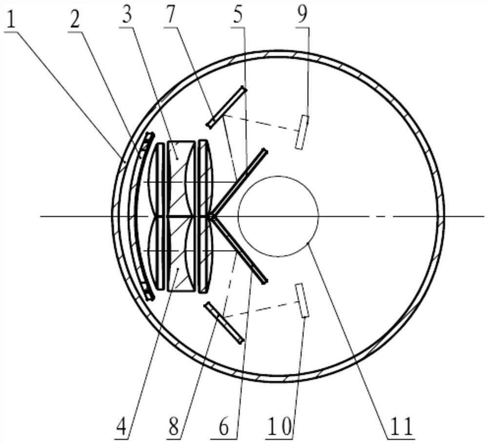
[0032] This embodiment 1 provides a laser radar optical system, including: a transceiving objective lens device and a ring-shaped hood 1 that is arranged outside the transceiving objective lens device; and a cylindrical compensation plate 2 is provided on one side of the transceiving objective lens device to Compensate the aberration of the ring-shaped hood 1 to the transmitting and receiving objective lens device.

[0033] In this embodiment, the transmitting and receiving objective lens device includes: a transmitting objective lens group 3 and a receiving objective lens group 4 arranged symmetrically; and the cylindrical compensation plate 2 is a rectangular cylindrical compensation plate or a circular cylindrical compensation plate or a square column Surface compensation board.

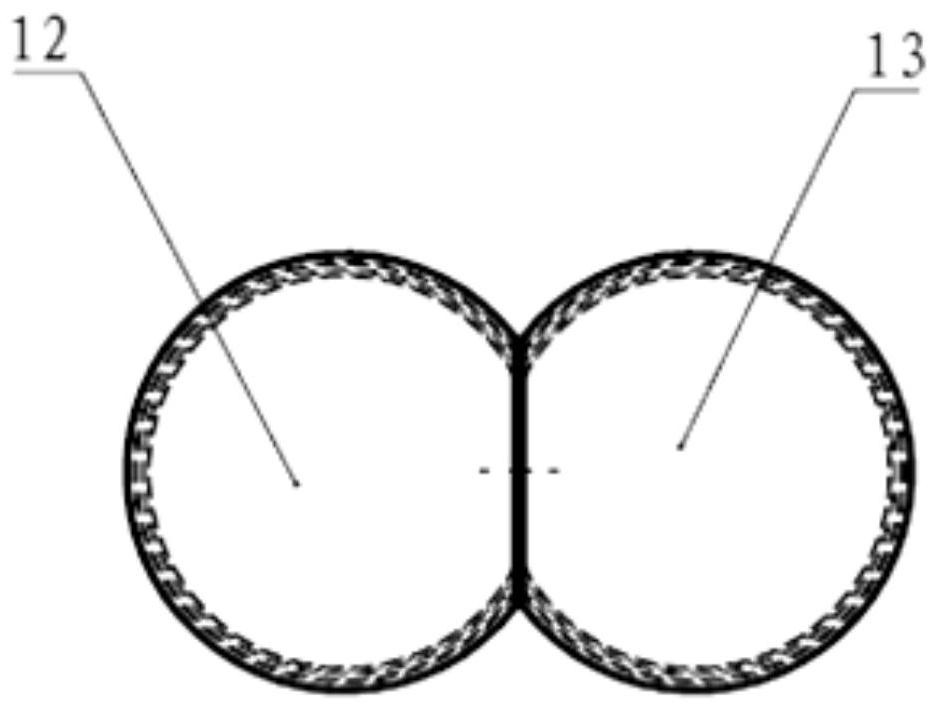
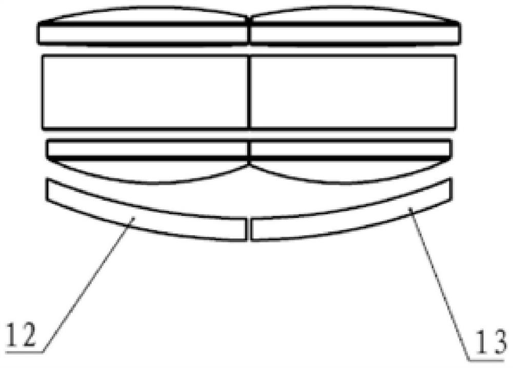
[0034] In this embodiment, the cylindrical compensation plate 2 can be a single piece, or it can be divided into two pieces.

Embodiment approach

[0036] Such as figure 1 As shown, the cylindrical compensation plate 2 is located on the side of the transmitting objective lens group 3 and the receiving objective lens group 4 close to the annular hood 1, and the inner arc side of the cylindrical compensation plate 2 faces the transmitting objective lens group 3 and the receiving objective lens group 4. .

[0037] When the cylindrical compensation plate 2 is a whole piece, as another implementation of the cylindrical compensation plate 2:

[0038] The cylindrical compensation plate 2 is located on the side of the transmitting objective lens group 3 and the receiving objective lens group 4 far away from the annular light shield 1, and the outer arc side of the cylindrical compensation plate 2 faces the transmitting objective lens group 3 and the receiving objective lens group 4.

[0039] When there are two cylindrical compensation plates 2, it is used as an embodiment of the cylindrical compensation plate 2:

[0040] Such as figure ...

Embodiment 2

[0055] On the basis of embodiment 1, this embodiment 2 provides an aberration compensation method for a lidar optical system, which includes: arranging a cylindrical compensation plate on one side of the transmitting and receiving lens device, and compensating the ring hood for the transmitting and receiving lens The aberration of the device.

[0056] Specifically, the specific structure and compensation principle of the cylindrical compensation plate of the laser radar optical system can refer to the description of Embodiment 1, and will not be repeated here.

[0057] In summary, the lidar optical system of the present application compensates for the astigmatism of the meridian surface caused by the annular hood by setting a cylindrical compensation plate. The transmitting objective lens group and the receiving objective lens group only need to use ordinary spherical lenses instead of high Order aspheric surface or a combination of aspheric surface and cylindrical lens can realize...


PUM


Abstract

The invention belongs to the technical field of laser radar and particularly relates to a laser radar optical system and an aberration compensation method thereof. The laser radar optical system comprises a transceiving objective lens device and an annular light shield arranged on the outer side of the transceiving objective lens device in a covering mode, a cylindrical surface compensation platewhich is arranged on one side of the transceiving objective lens device so as to compensate aberration brought to the transceiving objective lens device by the annular light shield. The laser radar optical system is advantaged in that astigmatism of the meridian plane caused by the annular light shield is compensated by arranging the cylindrical surface compensation plate, the transmitting objective lens group and the receiving objective lens group only need to use a common spherical lens and do not need to use a lens in a high-order aspheric surface or aspheric surface and cylindrical surfacecombined form; therefore, aberration correction of a 30-degree (+/-15 degrees) field of view can be realized, the using requirements of ranging transmitting and receiving are met, and the laser radaroptical system has the advantages that cost is low, and the measurement distance can reach 200 meters.

Description

Technical field [0001] The invention belongs to the technical field of lidar, and specifically relates to a lidar optical system and a method for compensating aberrations thereof. Background technique [0002] Lidar sensors are widely used in many fields, such as auto driving, surveying and mapping, three-dimensional modeling, etc. The most typical of a series of products produced by Velodyne in the United States is the 32-line lidar sensor, which adopts a non-coaxial system and a structure where the transmitting and receiving are adjacent. The entire transmitting and receiving system is integrated into a whole, which can rotate with the rotor and use a ring shape. The light shield encapsulates the transmitting and receiving system to ensure that the product operates under a series of complex environmental conditions. Due to the aberration caused by the annular hood, it brings certain difficulties to the aberration correction of the optical design of the transmitting and receivi...

Claims


Application Information

Patent Timeline
Patent Type & Authority Applications(China)
IPC IPC(8): G01S17/02G01S17/08G01S7/481
CPCG01S7/4811G01S17/02G01S17/08
Inventor 黄丽俐谢立峰刘伟
Owner CHANGZHOU XINRUIDE INSTR
Why Eureka
Try Eureka